A fantastic sounding VCO with 5 waveform outputs and an amazing hard sync sound! Quite easy to build too. This is a Kosmo project, not Eurorack. At least not this particular article. But this VCO will run fine on a dual 12V powersupply.
Finally a new VCO project on my website. These are always the most popular projects as I can see in the data I get from Google. And this is a really nice one too. It's a favorite among Psy-Trance and Techno producers! I'm reliably informed the hard sync in this VCO is regarded as being better than that of the Nord Lead. As is the FM function. That's saying something!
It has no less than five waveform outputs. The usual ones: Square/Pulse (with PWM), Sine wave, Triangle wave and Sawtooth wave and then there's the Rampoid wave. This is a mixture of the Triangle and the Sawtooth waves and there's a potmeter to go between the two which makes for some really cool wave shapes. See the scope pictures below.
One little side note though, this VCO is known for being difficult with tuning. It'll tune fine but the tracking over the octaves is not very precise. It's good enough to make the VCO useable of course but you will spend some time tuning and it won't be perfect. Just so you know!
When I was researching the VCF-1 filter (project 56) I found the 'Birth Of A Synth' website with all of Thomas Henry's projects on it and in the list was this VCO. I came across this design before and I always wanted to build it because the TH VCO-555 was also such a good design but also because of this VCO's famous Hard Sync sound.

The finished module.
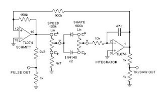
SCHEMATIC:
Below is the schematic for this VCO. The CD4046 is an interesting chip to use for a synthesizer VCO. It has an onboard voltage controlled oscillator and two types of phase comparitors. The IC has been used in some very cool Eurorack modules too, among them the Wiard Wogglebug.
The opamp used in the exponential converter, with the inputs of the VCO, is also an interesting one, the LF442. This is a modernised version of the LM1458. It has the same input characteristics of the LM1458 but only draws one tenth of the current. In addition the well matched high voltage JFET input devices of the LF442 reduce the input bias and offset currents by a factor of 10.000 over the LM1458. This ensures very low voltage drift and it also has very low equivalent input noise voltage for a low power amplifier. Seems like a good choise then ^___^
Here are the main features of the X-4046 VCO:
Exponential control and modulation.
Linear modulation.
Five unique waveform outputs: triangle, sawtooth,pulse with pulse width modulation, sine and variable rampoid. All waves are roughly 10Vpp through zero. (+/-5V)
And as the article in 'Birth of a Synth' states; one of the finest hard sync effects ever heard from a VCO.
THIS VCO WILL RUN ON BOTH +/-12V OR +/-15V. I built my VCO to work on +/-15V but I also tested it on +/-12V and it works just as well. Even the tracking wasn't much different when I switched to +/-12V so there's no problem building this for Eurorack. Some waveforms can be a bit lower in amplitude though. There's a video on YouTube showing a stripboard eurorack version being built. He uses lots of small pieces of stripboard with the potmeters soldered straight to them.
Schematic:

The KiCad version of the schematic:

LAYOUTS:
Below are the layouts for this project. As always they are verified. I used them for my build and I can tell you it worked flawlessly right from the get go. Not a single mistake! All I had to do was trim the waveforms into the right shape and the VCO was up and running. Oh and tune it for octave tracking of course.
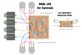
Here's the wiring diagram. We have 7 potmeters, 10 in- and output sockets and a toggle switch to wire up. It took me an afternoon and the next morning to get it done. I used 1M potmeters instead of 100K for all but the Frequency Coarse and Fine controls. The value of the panel potmeters makes no difference except the 'Skew' potmeter. That one needs to be 500K or higher. (I also used a 1M for that one).

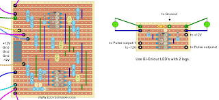
Stripboard only view:

I had some difficulty in placing the matched transistor pair Q4 and Q5 near to the opamp they need to be connected to, so I had to use some jump wires for that. The jumpwires are not shown in the layout. Instead I have marked the places where they need to go with 2 orange circles with the number 5 meaning this point needs to be connected to pin 5 of IC-4 and 2 yellow circles marked with the number 6 which needs to connect to pin 6 of IC-4. I used shielded wires and I connected the outer braiding of the wires to the ground strip underneath IC-4 (strip X) and these points are also marked with green circles with numbers in them. (Only ground the wires at one end)
However, you don't have to use shielded wires. Normal jump wires will work fine too. I just played it safe because the wires pass right over IC-1 but you can save yourself the trouble.
Here's a look at all the cuts and wirebridges that need to be put in place before you start putting in the components. There are 45 wirebridges to solder in:

A close-up of where the two jumpwires need to go. This image doesn't show the whole stripboard just a zoomed-in bit to show where the wires must go.:

Cuts only view, seen from the component side. As always, mark the cuts on the component side first with a waterproof Sharpie or Edding400 and then put a pin through the marked holes and mark them again on the copper side. Then cut the copper strips at the marked places. That way you have the least chance of making mistakes.

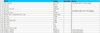
And here's the Bill of Materials. For the PTC I used the same one as I used on the 555-VCO. See project 37. That article has links to the webshop where I got them from They are 3300ppm instead of 3500ppm but that 200ppm difference you can ignore. It works just fine. You can also just put in a 2K resistor instead of the PTC.:

It is mentioned in the article that certain 4046 chips are better for tuning than others. I used a Texas Instruments CD4046 but that one is impossible to get tuned accurately. It was good enough for me but if you want the best chip for this circuit the ones to get are: National CD4046, Fairchild CD4046 or the Motorola MC14046. This last one is the best one you can get.
THE BUILD PROCESS:
As I mentioned before I had to use jump wires on the stripboard and because the wires pass right over, or near, the CD4046 I chose to used shielded wires. I connected the shielding to the bottom right ground strip (X). The outside shielding of the wires must only be grounded at one end. At first I used unshielded wires and actually it will work just as well so you don't have to used shielded wires. I just played it safe.
The transistor pairs need to be matched because one of the pairs makes up the current mirror for the 1V/Octave tracking and the other pair determins the shape of the sinewave. It's a classic triangle to sinewave converter design. I matched them by measuring the Hfe on my multimeter and choosing two that have the same value. You really should use the Ian Fritz method though. See the TB-303 filter project for an in depth explanation of how that works.
Just like in the 555 VCO, Thomas Henry uses a 2K PTC for temperature compensation. Luckily I still had a few left so I didn't need to order any. I recently ordered ten more because they are out of production. So when the shops are out of stock, that's it. No more PTC's. At least, not these ones.
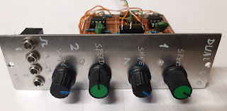
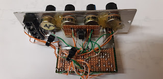
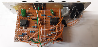
After I had finished making the stripboard, I made the front panel and put in all the potmeters and sockets. I made a special mounting bracket for the stripboard out of plexi glass. I took a small strip of it and bent it at one end in an L shape, using a heat-gun. then I glued small squares of plexiglass to the top and bottom ends so the stripboard could sit inbetween them. Then I hot glued the stripboard to the bracket. It works very well. Here's a front and back view picture to illustrate:

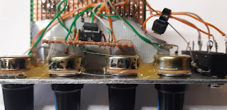
Here are some more pictures from the build process:
I had already started putting in some components before I remembered to take a picture of the stripboard with just the wirebridges.


Everything ready for wiring up. That took me an afternoon plus the next morning. All the socket grounds are connected together through one copper wire which then connects to ground on the stripboard.

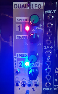
My faceplate design. Just white acryllic marker on black powdercoated aluminium, sealed with a clear lacquer coating, which is why it's so reflective :)

The finished VCO undergoing testing. I have a special power output on the side of my synth that I can use to test new modules. Very handy to have :)

TUNING THE VCO:
Calibrating the waveforms of this VCO is really straight forward.
For the different waveforms you just adjust the trimmers until the waveforms look good to you. The sinewave took a bit of time to get right but it's just a matter of trial and error. You need to set the offset voltage for the Triangle and Sawtooth waves so that the zero Volt line goes nicely through the middle.
Triangle connect does exactly what it says, it connects the upward slope to the downward slope. Very straight forward to set. One trimmer is for the upward slope and the other for the downward slope.
Tuning the VCO to track with the octaves is less straight forward but just a matter of using the V/Oct trimmer in combination with the Frequency controls on the front panel. The HF tracking has very little influence. I found it quite difficult to get this VCO in tune but that's a known characteristic of this VCO. It's not a fault in the schematic or layout.
I turned the Frequency fine control to get note C3 in tune and then I checked notes C2 and C5 and I turned the V/Oct. trimmer to get them closer to the true note. Then I checked all the octaves again.
I again set C3 in tune with the Freq control and turned the V/Oct. trimmer to get the others (C2 - C5) closer to where they need to be. I used the HF tracking to get better results on the higher octave but it has little influence.
I repeated this proces until I got reasonable results. I managed to get C3 to C5 in tune but C2 was about 20 cents too low. I just left it at that because it sounds just fine for my needs. I'll try and get it tuned better later. You really need to take your time for this.
What is very important here is the make of your 4046 chip. Look at the text under the Bill of Materials for a sum up of the best chips for this circuit. Motorola works best, Texas Instruments is not so good (and that's the one I had in stock and used).
These are the test results Thomas Henry himself got when tuning his VCO to track over the octaves:

Source: Birth of a Synth website.
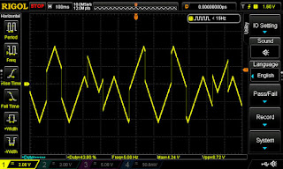
OSCILLOSCOPE SCREENSHOTS:
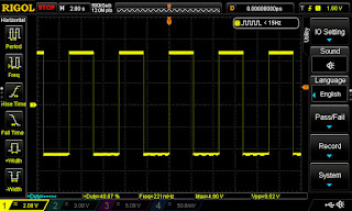
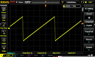
Here are the standard waveforms. The spikes you see on the triangle wave are a characteristic of the VCO. They are very fast and way beyond the human hearing range so no problem at all.
When I looked at the sawtooth wave I saw it had a bit of a wobble on the oscilloscope. However this changed to rock solid once I started playing the keyboard.

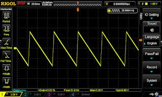
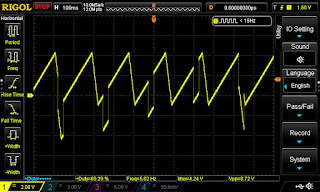
Here are some screenshots of triangle and sawtooth waves in the Hard Sync function for which this VCO is (rightly) well known. It sounds awesome!

Here's a test video showing the VCO in action through the Thomas Henry State Variable filter of the previous project.
Here's a little test video in which I try the famous Hard Sync function of the VCO. I must say this VCO paired with the State Variable filter is a killer combination. I'm using a sawtooth wave from the Thomas Henry 555 VCO into the Hard Sync input.
Here's the video where someone is building this VCO on small pieces of stripboard connected straight to the panel by means of the potmeters.
Okay that's if for this project.
If you have any questions or remarks please comment below or post them in the special Facebook Group for this website.