A revised version of the earlier 'Yet Another Sample and Hold' (YASH by Rene Schmitz) project.
This is the same core S&H circuit as the earlier one I published. That was one of the first projects I built and that was just over 3 years ago so it was time to update it. The things I added on myself were put together rather clumsily, especially the x1/x0.5 CV range switch that I put in. (The previous version works fine, don't get me wrong.) I have now replaced that range switch with a range potmeter so you can set the range to any level you want. The toggle switch for external or internal input has also been removed and instead I used the internal switch inside the External Clock input socket.
If you built the previous version then it should be quite easy to just replace the stripboard with this new version. You will have to make room for the extra Range potmeter but there will be a hole left over from the range switch so maybe you can drill out that hole to 7mm and use that for the potmeter.
SCHEMATIC:
Below here is the schematic drawing I made in Photoshop of this sample and hold circuit. It has the offset opamps and attenuation I designed added on, connected to the output of the LF398 Sample & Hold chip. The offset potmeter is a 100K linear type. You could use other values but that will alter the range a bit so I'd stick with the 100K. The Attenuation potmeter however must be a 100K one because it determins the gain factor of the opamp. If you put in a 1M for instance it won't only attenuate but also amplify which you absolutely don't want because the CV voltage will get way too high and it'll sound really bad connected to a VCO, if you get sound at all. There's a 470 Ohm resistor in series with the attenuation potmeter to make sure it doesn't go all the way down to zero and you'll always get a little bit of a signal. (I suppose you could get away with using an other value for the Range potmeter as long as the resistor between pins 2 and 7 is the same value as the potmeter. Then the balance (or ratio) between the two stays the same.)
Now, I know you are not really supposed to use an inverting amplifier with a feedback resistance that is lower than the input resistance. Normally Rf must be bigger than Rinput otherwise the opamp could draw too much current. I have however done some measurements and in this case it is absolutly fine. I used an NE5532 dual opamp in my circuit and the current always stays below 15mA.
The Offset control is included in the circuit so you can transpose the whole CV output up or down by as much as you like. This is handy if some of the notes produced are below the 0V line. In the normal case you would just hear a C0 note for those but if you give the CV an overall higher offset then all those notes will be audible. If you use the S&H to modulate a filter those negative voltages could sound really good so in that case you can dial in the effect you want to achieve with the offset control.
I put a 470pF capacitor over the output opamp because with testing I noticed a lot of little voltage spikes on the signal when I viewed it on the oscilloscope. The capacitor turned out to be a very good solution to suppress those little voltage spikes.
The Sample Rate potmeter needs to be a 1M Ohm linear type. I didn't have one so I used a 500K potmeter and that also works perfectly fine. Don't use any value lower than that though otherwise your frequency range will be very limited.
If you build this project and you find you can hear the pulse train in other modules, coming in over the power rails, then try putting a big electrolytic capacitor over the powerrails of this S&H module. Something like a 470µF or 680µF over the plus and the ground should do the trick. That should be enough but if the problem persists then also put one over the negative rail.
This circuit works equally well on +/-12V as on +/-15V. The current draw of the circuit is about +15mA for the positive rail and 10mA for the negative rail (maximum).

THE SCHEMATIC EXPLAINED:
The Schmitt-Trigger [A] at the bottom left is wired up as a Low Frequency Squarewave Oscillator and produces the clock pulse with the potmeter controlling the frequency. The clock pulse then goes to the switch connection of the external clock input socket. If there's no cable connected, the signal goes through the switch to the base of the transistor. Now when the clockpulse is high, it makes the transistor conduct and so the plus 15 Volt coming in over the LED is now connected to ground. The LED lights up and the voltage at the collector is practically zero (except for the voltage drop over the transistor) so the transistor actually inverts the clock pulse at this point. Then the pulse goes through a Schmitt Trigger inverter to invert it back to normal and then through a 470pF capacitor which changes the pulse (or actually squarewave signal) into a trigger signal. It then goes through two other inverters to cut off the negative part of the trigger pulse (a squarewave always produces a positive and negative trigger pulse, from the rising and falling edge of the squarewave, if it goes through a capacitor) to end up with the same positive phase it had at the beginning. It now goes into pin 8 of the LF398 and triggers it to take a sample of the voltage on pin 3. It presents this sample at pin 5 from where it goes into the two opamps to be buffered and more. At the first opamp we can introduce an offset voltage that will shift the whole pulse train up or down in voltage without changing the voltage difference between the pulses. In other words the offset voltage is just added (when positive) or subtracted (when negative) from the pulse train. Because this offset voltage goes into the inverting pin of the second opamp (summed with the pulse train) the working of this offset voltage is actually inverted but this just means the positive voltage needs to be connected to the counter clockwise side and the negative voltage to the clockwise part of the offset potmeter. The pulse train is inverted back to normal in the second opamp. At the second opamp we have a variable gain potmeter which has a maximum resistance which is the same as the input resistor which means the gain can not increase, only decrease. With this we can set the maximum voltage difference between the highest pulse and the lowest pulse generated. This then determins the range of the pulse train. So the pulses can for instance all be between zero and 1 Volt (one octave) or between zero and 7 Volt (7 octaves) and anything inbetween. This can give the pulses a more musical sound. There's a 470 Ohm resistor in series with the potmeter to make sure the gain can never be zero and we always hear a signal. The 470pF capacitor is there to suppress any voltage spikes on the output CV.
Now I know you're not supposed to use an opamp in this configuration as an attenuator. Rfeedback must always be bigger than Rinput; but I did test this setup and the opamp draws no extra current so it works perfectly fine.
LAYOUTS:
Here are the layouts I made for this project. I used these layouts for my own build so they are verified as always. Make sure you copy them accurately and it'll work first time.
Please keep in mind that the LED is a vital part of the circuit so don't leave it out! It's best to use a normal red, green or yellow LED for this either 3mm or 5mm.
This is the wiring diagram:
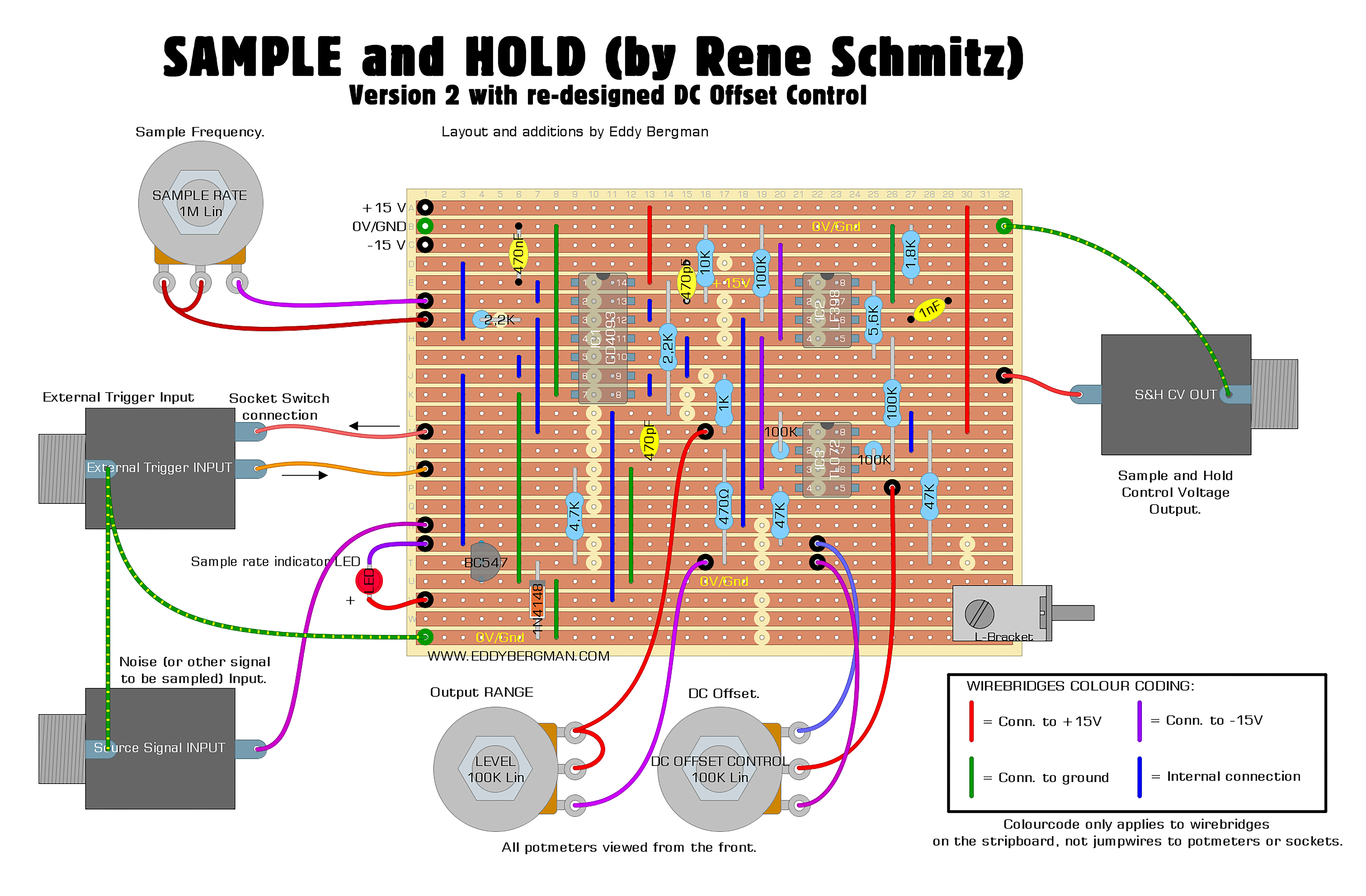
The Offset and Output Range options are of my own design. The Output Range is particularly useful. It determins the range between the lowest and the highest possible notes you will hear. You can set it so all the random CV Voltages (or notes) fall in the same octave or higher, upto a range of over 7 octaves. The inclusion of this option saves you from having to put the S&H output through an external attenuator to achieve this effect.
Here is the stripboard only view:

As always, mark the cuts on the component side and then stick a pin through the marked holes and mark them again on the copper side and then cut with a sharp, hand held, 6 or 7mm dril bit.

Here's the Bill of Materials:

OSCILLOSCOPE SCREENSHOTS:
Here are some screenshots from the scope:
In the shot below you can see the little voltage spikes I was getting when I first tested this circuit. They are the thin overshoots on the rising and falling edges and they also appeared in between in some cases.

Here's the result after I put in the 470pF capacitor over the output opamp. Nice clean CV output:

With all these images I used a sawtooth wave as 'Signal to be sampled', not noise. You can still get sort of random notes even without using noise on the input if the sample rate differs enough from the frequency of the wave you're using. However the paterns will be repeating, they won't be totally random, which can be good for creating melody or bass lines.
Here's a sawtooth wave being sampled at a very high rate:


PICTURES:
Here are some pictures I took while I was building this project:
The cuts and wirebridges ready:

Below you can see the components mounted except for the IC's. Note the vintage Polystyrene 1nF timing cap I used at the top right. It has a red stripe on it. That doesn't mean it's polarized. The stripe indicates which of the legs is connected to the outer layer of aluminium in the capacitor. That leg should always go to ground (or the lowest voltage potential). That way it acts as shielding to prevent hum. Now, if you have a cap that isn't marked but you want to find out which leg is connected to the outer layer and you have an oscilloscope then connect the probe to the capacitor; ground to one leg and probe tip to the other leg. Set the scope so it's quite sensitive and touch the capacitor body with your fingers. Now you become the signal source just by touching the capacitor body (not the legs). If you get a pronounced waveform on the scope then your probe tip is connected to the outer layer and the ground clip is connected to the inner layer. If you reverse them and touch the capacitor body again, you should get little to no deflection. Now you know the leg that outputs the biggest signal is connected to the outer layer and this leg should go to ground. However it is not necessary to do this procedure. I just wanted to tell you how you can find this out, but the capacitor will work fine which ever way you put it in because it's not polarized and this circuit is not that sensitive to hum.

The finished stripboard. I used the old Sample and Hold faceplate and soldered the new stripboard to the old wiring. This particular faceplate I made is a bit of a weird shape because of how I built my synthesizer. It actually sits in a little wooden plank above the other modules. You could say it's sort of a 1U module but for the Kosmo format :)

VIDEO DEMO:
I made a short video demo of the sample and hold in action. The S&H is connected to a Thomas Henry VCO. The input is white noise from the 5 sorts of noise module. The audio goes through the Steiner Parker filter and boy does it sound good!!
Finally I want to leave you with an excellent video by the 'Monotrail Tech Talk' YouTube channel which explains all the different things you can do with a Sample and Hold and discusses some awesome patches. Subscribe to him while you're there. It's an excellent channel for anyone into modular synthesis.
That's it for another one. If you have any questions please put them in the comments below of post them on the special Facebook Group for this website.
No comments:
Post a Comment
Note: comments are moderated and do not appear straightaway. Your first comment is not allowed to contain any links.