A redesigned version of the 8 step sequencer (project number 8) with external clock input option and offset control that allows you to transpose the sequence upto 3.5 octaves up or down.
[EDIT 1st - OCT - 2025] There is now a third version available which is based off the PCB version I made of this sequencer. I has a comparator on the clock input (internal and external) which lets you use any waveform as external clock pulse. You can find version 3 below the version 2 layouts.
-- Please read the entire article before you start building!! --
The sequencer project I posted when I was just starting out on this modular journey has rapidly become a very popular project on my website. I was however never really happy with that design. It was a bit clumsy and it had no extra features and although it worked like it should, it was never as good as I wanted it to be. It always nagged me.
So because it is such a popular project now, and using the knowledge I gained in the three years I've been building modules, I wanted to offer people something better to build. Something that I was sure wouldn't disappoint anyone building it. I'm really happy with how it turned out and I love using it. This is one of the few sequencers that can actually deliver negative voltages if you want to. Because a sequencer doesn't have to be used to make melodies or bass-lines, it can be a modulation source aswell. It really is a step above the basic baby 8 sequencers without using Arduino's. So here it is; the 8 Step Sequencer version 2.0
A NOTE FOR BEGINNERS: A sequencer does not actually produce any sound itself. It produces a stepped control voltage that can be patched into the CV input of a Voltage Controlled Oscillator and the VCO then produces the actual notes you hear. In a sequencer you can set each of these (8) steps manually to any voltage (and therefore any note) you want within 1 to 5 octaves.
This sequencer has a few advantages over the first one.
01 External Clocking. The sequencer can be clocked by an external source. In order to make sure this external clocking would work as well as possible I decided to use some of the hex inverters with Schmitt-Trigger inputs in the CD40106 chip (that we use to provide the internal clock signal) as buffers. A Schmitt-Trigger input has hysteresis. This means there's a voltage difference between when the hex inverter flips from on to off. For instance it might jump to off when the input goes over 6 Volt and turn on when the input gets below 4 Volt (remember it's an inverter). That's a 2 Volt hysteresis and this means it will be less susceptible to noise on the external clock signal. This turned out to work just like I hoped it did. I used two of these inverters switched in series so the (external) clock pulse itself is not inverted. I did a test and installed a bypass switch to feed the signal past the two hex inverters and immediately the external clocking stopped working for some signals, proving it's a good solution.
There is one little downside. The external clockpulse needs to be quite high in voltage. A 5 Volt pulse won't be enough. It should preferably be 6V or higher. I tried clocking it with the Behringer RD-8 but it wouldn't work. But when the pulse is high enough in voltage it won't matter what wave shape you use, it'll work. The Yusynth LFO with sync and FM input was able to trigger it if I used the triangle wave as external trigger.
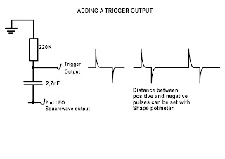
NB: One option to solve this problem: You can lead the trigger pulse through the Voltage Processor first and give it a little positive offset voltage. That way it will breach the 6V minimum threshold.
An other option would be to use an opamp as a comparator so that if the trigger rises above a certain threshold the opamp goes high and low again when the signal trigger goes below the threshold. I found a comparator design that works. You can put this on a tiny piece of stripboard and solder it to the input lug of the external trigger input socket and connect it to the external clock input. I would use a toggle switch to go between internal and external clock in this case. Btw, I have now tested this design and it works provided you connect the 741 chip to positive and negative 12 V as shown in the layout.
The clockpulse will come out with a 180° phase shift but it will be a 0 to +10V pulse.
I used this design for the clock input of the PCB version of this sequencer and it works great. It takes any waveform and changes it into a useable clock pulse.

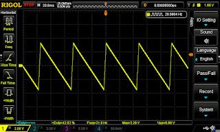
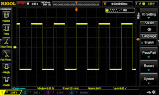
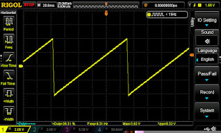
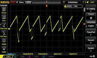
I took some pictures of the input (in blue) and output (in yellow) from the scope screen. In the first picture I used a squarewave going in and in the second a triangle wave. As you can see they are both converted into a nice 0-10Vpp clock pulse, although it is 180° shifted in phase but that's not a problem in normal use:


02 CV OffSet. This sequencer has an Offset feature. That means you can transpose the whole CV output chain up or down by as much as 3.5 octaves without compromising the Volt per Octave tracking. With the previous sequencer we were limited in the lowest notes by the voltage drop of the diodes on the potmeters. So it was never possible to get to note C0 which is 0.0833 Volt. But now we can trim the offset down and that will drag the whole sequence down in voltage making it possible to get to the lowest possible notes without screwing up the volt/oct. tracking and without need for special Schottky Diodes. I did use Schottky diodes (which have a voltage drop of only 0.2V) but only because I re-used the old sequencer for this build and the diodes were already soldered to the potmeters.
The offset feature is a game changer for this sequencer in my opinion because we can make really cool basslines or melodies and transpose it up or down without any problems. Naturally the output is not quantized so you won't land on true notes every time when tuning or transposing the sequencer. It's always a good idea to have a quantizer in your rig but they are too complicated for me to build as a DIY project. However, you can buy a eurorack quantizer like the Doepfer A-156 QNT (which I have in my Eurorack system) for €119,- (and that's a dual quantizer with extra options!) On the other hand, without a quantizer we can tune by ear and to what sounds right to us, without being bound by set scales. So there are advantages too to not having a quantizer. I always tune my sequencer with the Joyo tuner which I hacked for modular use (click here for that project.)
The offset feature can also be very useful if you use the sequencer as a modulation source for instance to modulate the filter. You can drag the sequence down so some steps have a negative voltage and others a positive voltage and so create weird VCF responses.
For those of you interested, the CV voltage (the sequence) goes into the inverting input of the offset opamp and the offset voltage goes into the non inverting input. Then in the second opamp the CV voltage is inverted back to normal again while the offset voltage now gets inverted. That's why the wiring of the offset potmeter is the other way around from normal. The output opamp has a 470pF capacitor over the feedback resistor to suppress little voltage spikes which I could see on my oscilloscope, just like in the Sample and Hold v2.0 project. The 470pF gets rid of that very effectively.
I previously had a section here discussing an external speed control using a vactrol over the speed potmeter, but I took that section out. It's too clumsy and I myself don't use it. If you want external speed control over this sequencer then use an external clock source from a LFO with CV frequency control. Like the YuSynth LFO from project 30 which has an FM (Frequency Modulation) control meaning you can change the frequency with a control voltage.
SPEED CONTROL and the TUNE/RUN switch.
The sequencer has a speed control potmeter that will go from 1.34 seconds (746mHz) to about 185Hz. If you want that speed to be lower you can add a 4,7µF cap in parallel over the 10µF cap to bring that speed down to about 2 seconds which is slow enough and it will still be able to go very fast too.
It also has the tune/run feature of the previous sequencer to make tuning each step easier. The old procedure was to just set the speed very slow and then stop the sequencer at each step so you could tune it. Then you would switch to Run to go to the next step and stop it again to tune that one. With this new version you can use the push switch to manually go through the steps to tune them.
I had some problems with stopping the sequencer in the beginning. The sequencer would continue running even after switching it to Tune but the solution was simple. When switched to Tune the clock input must be grounded (which I hadn't done). I used a 1K resistor for that, connected to the switch and to ground. This is why it is important to connect the wire that is in direct contact with pin 14 of the CD4017 to the middle pin of the Run/Tune switch. Otherwise this doesn't work.
A word about tuning: it's not the easiest thing to tune this sequencer to an exact note due to the fact we have 7 Volt to deal with and a 100K potmeter to set it to an exact note. In the 1V/Octave standard the difference between two notes is only 0,1666 Volt. And between two half notes only 83,3 thousandth of a Volt. That sort of resolution is difficult to achieve with a normal potmeter. However it is not impossible. It takes little touches of the potmeter but, as you can see in the demo videos below, it can easily be done with a little patience and accuracy. This problem goes for all Baby 8 sequencers, not just this one and I use mine a lot and I've always managed to get it sounding really good and in tune. This is also why the CD4017 is powered with 8 Volt. If you gave it 12V the resolution would be much worse. As I mentioned earlier, you could buy a cheap eurorack quantizer which would help a lot with accurate tuning but that's up to you. Or, an other really helpful tool to have is the Joyo Tuner, hacked for use with modular synthesizers. It's what I personally use to tune my sequencer.
MOMENTARY SWITCH
I had a lot of problems in the beginning, implementing a momentary switch into this design. With that switch you can advance one step each time you push it to switch between channels to make tuning easier. The problem was that I forgot to ground the clock input of the CD4017 when the sequencer is in Tune mode. I made some changes and I connected a 4K7 resistor to the 'Run/Tune' switch that grounds the clock input. After I had done that I thought I'd try to get the momentary switch working. I connected a momentary switch between +8V and the pin of the 'Run/Tune' switch that has the 4K7 resistor connected to it. But when I switched to Tune mode it still kept jumping several steps when I pushed the switch. I figured this must be due to contact bounce in the switch. To counter that I soldered a 470nF capacitor in parallel over the momentary switch and that did the trick. Now it works like it should.
SCHEMATIC:
Here is the schematic for this sequencer. I made it using Photoshop.
I have only drawn two of the output steps coming out of the CD4017, with the LED, the potmeter and the diode connecting to the CV Rails. You need 8 of those to complete the 8 steps of the sequencer of course. The CV Rails is just a bare copper wire, that runs beneath the faceplate, where the outputs of each of the 8 steps are soldered to. From there a wire then connects the CV Rails to the offset opamp on the stripboard.

The addition of the offset feature means that when the sequencer is switched off, there would normally still be an offset voltage on the CV output! I have routed the CV output through the same switch as the one we use to switch the sequencer on and off. So when we switch the sequencer off the CV output is also interrupted. That's why we need a dual pole switch for the on/off.
I have recently edited the schematic a little. I put the grounding resistor for the clock pulse right at pin 14 of the CD4017 and I took out the whole external speed control thing with the vactrol. I don't like that solution so please don't use it. If you want variable speed use an external clock pulse from a CV controlable LFO.
ALTERNATIVE SPEED CONTROL:
I found a better way to do the speed control on the sequencer. Instead of just a 100K pot and a 10µF cap, use a 500K potmeter with a 10K resistor in series and then use a 4,7µF cap like in the picture below:

This gives a better and smoother speed control. This is not implemented on the stripboard layout so you'll have to make these changes yourself if you think you need it.
I later altered the values to 1µF for C4 because the speed was very slow over 3/4th of the throw of the potmeter. This works much better. You must leave the 10K in series with the potmeter otherwise the clock frequency will go too high and the sequencer stops. In my sequencer this still happens if I turn the speed up and the potmeter is at the 4 o'clock position. The clock input is overwhelmed.
The connections of the rotary switch follow one step behind the connections of the potmeters. So step 1 is reset by the pulse from step 2 so be very accurate in that. I got that wrong in the previous version.
There are two diagrams on the layout below explaining where all connections go for the potmeters and for the rotary switch.
In the schematic I use normal 1N4148 diodes but in the layout they are named as 1N5819 Schottky diodes. Go with the 1N4148 diodes. I only have Schottky's in the layout because that's what was already in there from the previous version of this sequencer. Schottky diodes have a lower voltage drop than normal silicone diodes but now that we have the Offset feature the voltage drop is no longer an issue.
It is totally unnecessary to include transistors in the output steps to feed the LEDs. I just put 10K resistors in series with the LEDs to keep their current draw to a minimum and because opamps don't draw any current at all the LEDs do not pull down the voltage when they are on. The LEDs are fed with 8V from the outputs of the CD4017 and with the 10K resistors they are still bright enough. It is however important that you do NOT use any LEDs that draw a lot of current like blue LEDs or bright white LEDs. Those may draw the voltage of the CV output down. Not only that, in the long run they can heat up the CD4017 so much that it fails. The outputs from the CD4017 can't deliver more than 6.8mA maximum with a 15V power supply. (see datasheet)
(The PCB version runs on +/-12V and uses a 7805 to feed the CD4017 and the potmeters (5 octaves) and it has 4K7 resistors on the LEDs.)
The current draw of this module is incredibly low. The +12V part only draws 6 mA in normal use and with the internal clock at full speed it draws 10 mA. The negative side, -12V, only draws 0.73 mA! That's 730 µA! Regardless of the clock-speed. That's nothing! So you can easily run this module on two 9V batteries and use it as a stand alone sequencer should you wish to do so, and your batteries will last for months. (use 2 batteries to create a dual voltage supply)
The Gate output produces gate signals that are exactly half the length of a single CV step. In other words they have a duty cycle of 50%.
LAYOUTS:
Below is the original version 2 layout I made for this project.
If you scroll further down, you'll find an 'Alternative version 3' which is based on the PCB's I made in the summer of 2025. I posted the KiCad schematic and I made a stripboard layout based on that schematic. So that is the version 3 but the rest of this article deals with version 2. I hope that's not too confusing. If you want my opinion then build the version 3 layout. However I have not yet had that layout verified! So please check your work against the schematic as you go. (The schematic is verified).
If you built the first version of this sequencer earlier, then it's really easy to replace just the stripboard with this version two one. You only have to make two extra holes in the face plate for the external clock input socket and for the External Speed CV input (or three if you want to include the 'end of cycle' trigger output) and all you have to do is reconnect the old wiring to the new stripboard,
In this layout I connected only the first 3 steps to show you how it should be done. You can easily repeat these connections for the other 5 steps. I did this to prevent the layout becoming a mess of hook-up wires. Follow the numbering in the text at the bottom right to connect the potmeters and rotary switch pins to the correct pins of the CD4017. Of course you could include the left over two pins from the chip to make it a 10 step sequencer but 10 steps don't sound right. Normally you got 4 steps to a beat so 8 steps sounds better. If you do want to make it a 10 step sequencer you will need a rotary switch with 11 positions! Otherwise, if you use a 10 step switch, the CD4017 will be reset at step 9 instead of 10. In case of a 10 step sequencer you don't need a reset pulse because the CD4017 only goes to 10 steps so it will reset itself.
This sequencer is equipped with an ON/OFF switch so you can easily introduce it into a jam session by flicking the switch. That way you can leave it patched up and have it instantly available when you need it. The ON/OFF switch for this module is located behind the voltage regulator and that is done on purpose. If you put it before the regulator the sequencer would shut down very slowly because the 470µF capacitor discharges very slowly. So you would hear the sequence getting slower and slower and the notes going out of tune and fading out if you switched off. With the switch behind the voltage regulator the switch-off (or on) is instantly done. The regulator itself doesn't use any current when not in use and this has the added bonus that the sequencer starts up immediately too if you switch it on.
If you want to include 'Mute' switches for each step then I indicated on the layout the best place to put them (after the diode of each step). If you mute a step there will still be a gate signal for that step present on the Gate output.
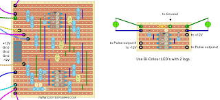
Wiring diagram:
I show only 3 of the 8 steps in this layout to avoid it becoming too cluttered with hook-up wires. It's already a mess of wires. Just repeat the LED, Diode and Potmeter combinations five more times. The list at the bottom right tells you where to connect each step. This layout also contains an LED pinout diagram.
All potmeters are viewed from the front!

(The connections of the rotary switch follow one step behind the connections of the potmeters to the CD4017. That's why there are two columns of connections on the lower right.)
Please be aware of the wiring of switch 1a and 1b. The switch interrupts power to the CD40106 and CD4017 chip and also the CV output.
THE LAYOUT BELOW IS THE SAME LAYOUT AS ABOVE ONLY THE POTMETERS ARE NOW SEEN FROM THE BACKSIDE! I thought this might be helpful for some people when wiring up the panel.

NOTE: The position of the Gate output wire as I built it here will mean that when you set the sequencer to 'Tune' you won't get a gate signal output if you push the momentary switch. If you do want a gate output when in tune mode then de-solder the wire that goes to the gate output socket out from the stripboard and solder it to the middle pin of the 'RUN/TUNE' switch or to the right hand side of strip L (pos. 22 to 38). That way you'll always have a gate signal when the sequencer moves from one step to the next. I don't think it's necessary to make this change but I just want to mention it here.
Wiring procedure:
When you are ready with the stripboard and ready for wiring, make the face plate first and put all the potmeters, sockets. LEDs and switches in. Then wire up the potmeters with the diodes to the CV rail (a bare copper wire) that connects with a wire to the stripboard. Wire up all the LEDs too. Now loosely connect the stripboard to the faceplate and then you can wire everything up to the stripboard very easily.
The mysterious grey component at the bottom middle is an L-Bracket to mount the stripboard to the faceplate. But you can use any method you want to connect the stripboard to the faceplate. In my build the stripboard is mounted parallel to the faceplate with one M3 threaded stand-off. The wiring also helps to keep it in place nicely.
TIP: You could connect a socket to each of the 8 stages (before the potmeter) and so use this as a trigger sequencer too.
Stripboard only view:
Below is a close-up of the stripboard. The voltage regulator and the big 470µF electrolytic capacitor plus the other two 10µF caps are quite crammed in together on the top left of the board but it shouldn't be a problem. The voltage regulator doesn't even get warm in normal use so it doesn't need a heatsink. You could also use the smaller 78L08 types that look like a TO-92 package transistor.
You do need the big 470µF cap in there otherwise the pulsetrain could be audible on the voltage rail. In fact, I myself used a 2200µF/16V cap in that position to be on the safe side. (The light blue edges of the caps indicate the negative pole.)

Cuts and Wirebridges:
Below are the cuts and wirebridges seen from the component side. As always, mark the cuts on the component side first using this layout and then stick a pin through the marked holes and mark them again on the copper side and cut the strips by hand with a sharp 6 or 7mm drill bit. That way you have the least chance of making mistakes. Check the cuts afterwards with the continuïty mode of your digital multimeter or a strong magnifying glass.

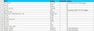
Bill of materials. This is a new version.
I have put some components in this b.o.m. that are only needed in the version below. Please double check with the schematic of the project you're building for the components so you don't miss anything.
In my own sequencer I actually have two Gate Out sockets, just connected together. I found it useful in some patches to have two so order 5 sockets it you want to include that option.

ALTERNATIVE SCHEMATIC and LAYOUT (version 3):
Here is the schematic I used for version 3 of this sequencer (PCB version) and it is working perfectly I can tell you. It has the comparator I mentioned earlier, on the clock input so you can use any wave as a clock source. The comparator will convert it to a usable squarewave. The CD4017 is running on just +5V in this design so we have good resolution on the 8 note control potmeters plus it has the offset control to reach even higher notes of to go right down to note C0. Here it is:

The jumpers after the diodes are for mute switches, should you want to include them. As you can see the clock pulses go through an opamp comparator, even the internal clock which is connected to the socket switch of the external clock input. So if no patch cable is inserted there, the internal clock is switched to the comparator and from there to pin 14 of the CD4017. Because the CD4017 is running on +5V we can not feed it with a 10V clock pulse. That's why I included a 4K7 resistor with a 5.1V zener diode that cuts the amplitude of the clock pulse down to 5.1V so the chip doesn't get damaged.
HERE IS A FALSTAD SIMULATION OF THIS CIRCUIT: ---- CLICK HERE ----
(click continue to your destination if asked.)
I made a layout from this new schematic. The wiring of the potmeters and the rotary step switch is all the same as in the previous layouts. These are updated versions, the previous layouts had a few mistakes in them. Pin5 of the TL072 wasn't grounded and the speed and offset pots were wired in reverse but it's all been updated now so it should be good now.
Wiring:

Stripboard only:

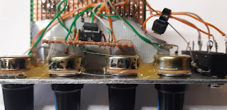
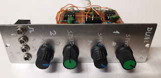
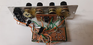
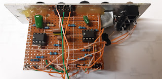
Pictures:
Here are some pictures of the stripboard during the building proces. My stripboard had one little error in it which was spotted by one of our awesome Facebook members and that was that the copper strip connecting pin 8 of the CD4017 to ground had a cut in it. I built it with that error included and strangely enough it worked normally but I have now corrected it. I made an other error in this picture, the connection to +12V for the TL072 chip has been forgotten. (Holes N-41 and O-41 in the picture below) You can see it's added in the picture below it:


OSCILLOSCOPE SCREENSHOTS:
Here's a picture of the 'End of Cycle' trigger pulse that resets the CD4017. You can see how enormously fast this pulse rises and falls, within 280 nanoSeconds. (Ignore the yellow line above it.)
(I dropped this feature from the design but if you want an output for this pulse, tap it from the wiper of the rotary switch and route it through two left over 40106 inverters to an output socket).

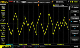
Here's an example of a CV output sequence with potmeters set to various notes. As you can see the maximum output voltage is around 7 Volt (or 7 octaves) when the potmeter(s) are fully set clockwise and goes all the way to 0V with the potmeter(s) fully closed and a little negative offset applied. You can easily set or adjust this just by ear.

And this is a scope image of the clock pulse generated by the CD40106 as it enters the CD4017:

DEMO VIDEOS:
Finally, here's a little demo video showing the sequencer in action connected to a Thomas Henry VCO-555 and the Steiner Parker filter.
If you can't see the video above, here's the link: https://youtu.be/lcsw4txNoj
And here's a video of me trying to replicate the intro from Vangelis' Spiral. I always loved that sequence. The sequencer is again connected to a Thomas Henry 555-VCO and the Steiner Parker filter. Plus a little echo from the FX Unit:
To get this sound connect the sequencer CV out to the Exp. FM Input of the Thomas Henry VCO-555 (attenuator fully clockwise). Take the Sawtooth output and patch it to the input of the Steiner-Parker filter set to Lowpass. From there into the VCA and add some echo with preset 59 of the CaraOK FX Unit. Just add a little of the echo. Play with the VCF Cut-off to get the variation in the sound.
To program that pattern, tune your steps as follows: F2, C2, F3, C3, F4, C4, F5, C5And finally a test with Vangelis' Dervish-D intro. Make sure you use a fast envelope on the VCA because the notes need to sound punchy.
The note progression for this sequence is: C#3, C#3, C#4, G#3, B3, G#3, F#3, E3
CLOCKING AT AUDIO RATES or the SEQUENCER as WAVEFORM GENERATOR:
I was watching one of Sam Battle's (LMNC) videos and he talked about using a Baby 8 sequencer as a waveform generator. If you clock this sequencer at audio rates you will in fact get an other oscillator with a waveform that is cut into 8 steps (or less) and adjusting each step will change that part of the waveform and with it the overall sound of the oscillator/sequencer. The sequencer is clocked by a VCO so the clock frequency will change with the note you play so it will track over the octaves and the CV out from the sequencer can go straight into a filter.
It looks like a fun thing to experiment with. I'll link to the video in question below here, where Sam explains how this works. The video should start at 9:25:
I've not actually tried this method on this sequencer and I'm not sure it will cope well with high clock frequencies because of all the schmitt trigger stages inbetween. This might work better with a direct outside clock input to the CD4017 (which is not included in my design.)
KORG SQ-1
TIP: Finally here's a little tip for all you who want to take sequencing a little further. Buy a Korg SQ-1 sequencer. It costs less than €100,- and will give you 16 steps or 2x8 steps and a miriad of options. This is of course not a module but a stand alone sequencer but it is very small and runs on 2 AA batteries. The case is made of metal and the thing weighs over a kilo! It outputs quantized CV voltages and you can set the voltage range to upto 8V. A lot of performers use an SQ-1 in their live sets. It also works very well with the modular synthesizer I've built from all these projects.
If you want to know more about this easy to use sequencer then just Google "Korg SQ1" or even better do a search on YouTube and you will find a sea of videos on this machine that will tell you all you want to know.
Okay that's it for the Sequencer V2.0. As always, if you have any questions or remarks about this or other projects please comment below or post on the Facebook Group for this website.