Showing posts with label low. Show all posts

Saturday, 15 January 2022

Synthesizer Build part-47: DUAL LFO for EURORACK.

A simple LFO with pulsewave (with variable pulse width) and a seamless transition between a Ramp wave, Triangle wave and Sawtooth wave using one potmeter. With LED rate indicators and Speed and Shape controls.

Well what more is there to say about this LFO. It's such a simple design that I could easily fit two of these on a small piece of stripboard and still have it small enough to fit a normal Eurorack case. The circuit is derived from the 'Utility LFO' by Ken Stone which is a larger version of this LFO. 
I now also have a project for the complete Utility LFO and it's even smaller than this one and a panel width which is only 1HP wider at 9HP.  Go to project 50 for that.  
This LFO is still useful on its own though because it is so small. It can easily be incorporated into other projects as an on-board LFO for instance.

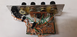
The depth of this module is 55mm. I made the panel 4CM wide, that's 8hp, and I put the potmeters to one side leaving enough room to glue the stripboard straight to the back of the panel at a 90° angle using hot glue. All the output sockets fitted nicely next to eachother at the bottom.
Naturally you can just as easy build this module in the Kosmo size or run it on 15V. If you do, you need to keep to the resistor values as they are in the schematic, not the layout because as I mention further down, I changed the 1K output resistors to 1K8 to get a nice +/-5V output signal. If you power this with 3 more volts you probably don't have to do that. Do some testing first to make sure though.

I tried my hand at using Falstad recently and tried to make a simulation of the complete Utility LFO circuit and it was surprisingly easy to do. 
So here is my very first ever Falstad simulation: --- CLICK HERE ---

Here's the schematic drawing of the dual LFO circuit:
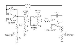

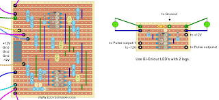
The module consists of two of these circuits on a single piece of stripboard. I placed the LEDs on a separate piece of stripboard with a dual opamp, the good old TL072, and I used bi-coloured 3mm LEDs in red and blue. I drilled two 3mm holes to the left and in the middle of the first two- and last two potmeters for the LEDs and glued them in place with hot glue so the little print sits over the potmeters. See pictures below for illustration. Btw, you can use any dual opamp chip for this circuit as long as the pinout is the same; like the TL082, NE5532, LM358 etc.

LAYOUT:
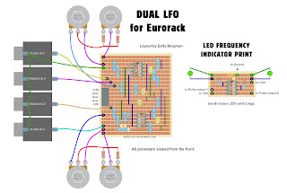
Here is the layout I made for this Dual LFO. As always, the layout is verified. I used it for my build. I placed the Eurorack powerconnector on the left side for better access. In my build it's on the other side and very near the panel. Not a good place for a power connector but you only find these things out when you start building it. See, I make the mistakes so you don't have to LOL! (I hot-glued the print to the back of the panel with the righthand side closest to the panel.)

Stripboard only:

After doing the first tests I found the output voltages a bit on the low side. They were just +/-3,24V so I decided to experiment with the 1K resistors between the outputs and ground. I tried several values and I ended up using 1K8 resistors. That brought the output voltages to a nice +/-4,8V. Almost 5V so that's perfect for eurorack. If you want that voltage to be even higher in your LFO then experiment further with making the resistor(s) between the output socket and ground even higher in value.
I wanted to make one of the LFO's a bit slower than the other to give me a wider overall range so I used a larger capacitor for LFO number one. I used a 147nF and that made it perfect for my needs, between 0,2Hz and 10Hz. In the layout both timing caps are 47nF though.
 
TECHNICAL DATA:
Here are some measurement results for this Dual LFO:
Duty cycle of squarewave is 5% to 95% this varies a bit with the frequency but not more then 2%.
Lowest frequency: LFO-1 = 0,219Hz  LFO-2 = 0,653Hz (changed timing cap of LFO-1 from 47nF to 147nF)
Highest frequency: LFO-1 = 9,82Hz   LFO-2 = 34,2Hz
Output voltage is +4,8V or 9,6Vpeak-to-peak. That's after changing the 1K resistors in the schematic for 1,8K ones. Otherwise the voltage was just 3,2V and 6,4Vpp.
Current draw: positive: average 12mA max.: 18mA
                       negative: average -13mA max.: -18mA

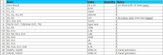
Here's the Bill of Materials:

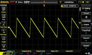
Here are some screenshots from the oscilloscope with some measuring data underneath the images. Some images may still show the lower output voltage but that's been fixed:
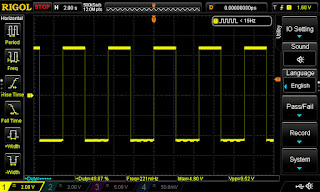
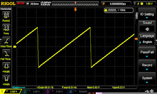

The following are screenshots from the oscilloscope showing two signals, one from each LFO, being combined in a simple passive multiple. A squarewave and a triangle wave each at different frequencies. The results are pretty cool looking:
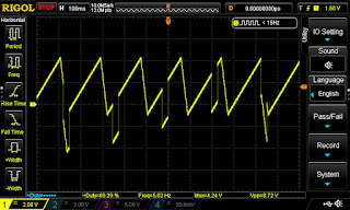
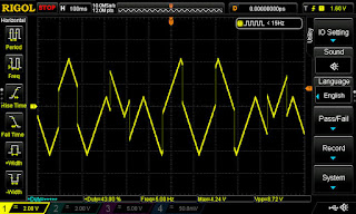

In the top picture you see more of the waveform in the positive voltage region and very little below zero Volts. You can set that with the shape potmeters to your own liking or best sounding result. As you can see this makes the Dual LFO module much more versatile as a modulation source. Plenty to experiment with.


PICTURES:
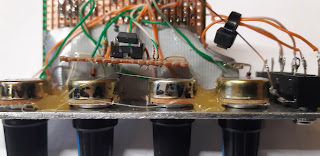
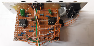
Below are some pictures of the finished stripboard. I took these before I changed the 1K resistors to 1K8 ones. In the top picture and the 3rd one you can see how I mounted the little board with the bi-colour LEDs. It rests above the middle two potmeters and the LED's are bent backwards over the sides of the stripboard and go straight into the holes in the panel and are secured with hot-glue. The little board itself is not mounted in any way. It just relies on the LEDs to keep it in place.
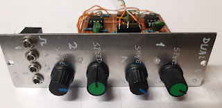

This time, instead of spray-painting the panel I decided to keep it blank aluminium and I used an engraving tool to put the text on. That didn't work too well and it didn't look good at all so I printed some labels I made in Photoshop, laminated them with Scotch Tape and put some double sided sticky tape on the back and I put those on the panel. That looks much better. 

TRIGGER OUTPUT
A few days after completing this build I added a trigger output to this module. I connected it to the squarewave output of the second LFO (the faster one). I thought it might come in handy to have a trigger source. You can see in the picture below how I did that. It gives of both positive and negative trigger pulses of 5V and a length of about 4mSec.  If you're thinking of putting in a diode to only get positive pulses forget it. That won't work. It'll kill off the pulses completely. If you turn the Shape potmeter the positive and negative pulses will move further away or closer to eachother. Just like the rising and falling edges of the squarewave with different pulsewidths.
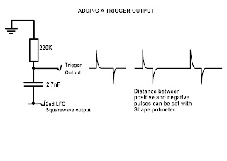

(The above drawing actually translates to a high pass filter with a cut-off frequency of 268Hz. So it filters out the actual square- or pulsewave and only lets through the initial harmonics of that wave, creating this spike pulse trigger response, but you can forget about this theory. This is not important.)

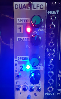
Here's a look at the final panel with trigger output. I just made some labels with text to put on the panel. Looks better than the engravings.


One other thing worth noting is that because we have two LFO's on one board, they will very slightly influence eachother. What I mean is, if you have one LFO running at almost twice the speed of the other, the faster one will adopt some multiple of the rythm of the slower one if you set the speed to some value close to that. That's a form of resonance and I won't get into the technicalities of that but it's quite easy to set an LFO at twice or 4 times the speed of the other because they share the same circuitboard. It's the same idea as when you have a group of people walking together and they all start to walk at the same pace. That's also a form of resonance. Don't think this will be an obvious thing to observe. The occurrence is very subtile.

Okay, that's number 47 done! A very useful little module and I saved a few bob by building it myself instead of buying a dual LFO module. Okay it doesn't have any fancy extra's like synchronization but that's okay by me. I think I'll mostly be using this as a clock source and some random modulation. That's why I made both LFO's run at different frequency ranges.

If you have any questions or remarks about this or any other project on my site please comment below or post in the FACEBOOK GROUP for this website.

If you find these projects helpful and would like to support the website and its upkeep then you can buy me a Coffee. There's a button for that underneath the menu if you're on a PC or Mac. Or you can use this PayPal.Me link to donate directly. All donations go towards the website and projects. Thank you!

Thursday, 7 May 2020

Synthesizer Build part-31: NOISE MODULE with 5 TYPES OF NOISE + Random Gates.

A very easy to build noise module with 5 different sorts of noise, two of them being 'Grainy' noise with adjustable graininess.  Works on dual 12V so Eurorack friendly.

(The Random Gates section is located half way down the article)
This is a module I adapted from the MFOS Noise Cornucopia schematic by Ray Wilson. It's turning out to be quite a popular project because I'm getting lots of feedback from people who built it and are really happy with it. Especially the addition of the Grainy Noise.
Please note this project is meant to be built with through-hole components. The opamp section isn't that critical but the transistor that generates the noise should be through-hole with the collector leg cut off completely.
So, I needed a good noise source in my synth and this one seemed perfect. The original schematic has a random gates section which I didn't need but which you can easily add on if you want it. But I left that out. (I made a separate layout for the Random Gates Generator section which you can find further down the article) I also changed the transistor used to generate the noise and I changed the way the transistor is integrated in the circuit. My way is simpler and generates 200mV worth of noise right at the emitter of the BC547. The transistor's Emitter-Base breakdown voltage is exceeded thus the transistor is operating in avalanche mode, creating nothing but pure noise.
This was a one day build for me. I spent the morning adapting the design and making a stripboard layout. Then I built it in the afternoon and by 8pm that same day I had a good functioning noise module built into my synthesizer. The layout I made worked right from the start. No troubleshooting needed.
In the layout below the transistor is shown as a schematic symbol, and not as it's normally shown in the TO-92 package, to make it clear that the collector is not connected. In fact, you need to cut off the collector leg completely to stop it working as an antenna. I've put the pin-out of the BC547 in the layout to make this extra clear. You might need to choose a BC547 that gives you the best noise results. I heared through feedback comments that there can be differences between transistors but you should get noise with any transistor. It's just that some transistors produce more noise then others. I myself put in the first transistor that I had, and didn't choose between them. It worked fine as you can se in the video. Should you experience hum or something, from the power supply, then you should resort back to the transistor arragement in the original design as shown in the original Noise Cornucopia Schematic

Here is the verified layout.

(Last revised 16-May-2020: Added grounding wires to output jacks and pinout to noise transistor.)

Stripboard only. 
For extra clarity: connect the 'Base [B]' of the transistor to copper strip 'I' and the 'Emitter [E]' to copper strip 'G'.
The cut on position D17 in the layout above, has been moved to position D21 to make it more visible.


Below is an overview of the cuts and the wirebridges alone. This is seen from the component side! As ever, mark the cuts on the component side with a black waterproof marker and then stick a pin through the marked holes and mark them again on the copper side. Now you can cut the copper at the marks with a sharp hand held 6 or 7mm drill bit.


Bill of Materials. Instead of the TL084 and TL082 you can also use the TL074 and TL072 opamps:


Here is the altered schematic, made from the original Noise Cornucopia design:


Btw, if the BC547 doesn't produce noise for you, try a 2N3904. Remember it has the opposite pinout of a BC transistor. E and C are changed around. Not all transistors are created equally and some produce more noise than others. Start with BC547's though. That's what the circuit is designed for. If that still doesn't work try connecting the base or the transistor with a 10K resistor to negative power. That's how it's done in the original Noise Cornucopia schematic. 

This is the original Noise Cornucopia noise stage. I used a simpler design which worked fine for me but if you can't get noise from your circuit, try this as an alternative. 

The noise output from the transistor goes through a highpass filter consisting of the 100nF capacitor and the 2 MegaOhm resistor. This creates a filter cutoff frequency of 0.8Hz letting through all the frequencies and rejecting any offset voltage. Should you experience an offset voltage after the filter then lower the resistor value from 2M to 1M. That will make the cutoff frequency 1.5Hz.
I changed the 500K trimmer, used to set the amplitude of the noise, for a 200K panel potmeter so you can use it as a level control on the front panel. In my panel I used a 500K panel potmeter but that really is too high a value. When I turn the potmeter 1/3rd open, the amplitude reaches it's maximum at 10V peak-to-peak and the rest is just maximum volume and starting to clip, so I think it's better to use a 200K potmeter. (However I haven't tested it with a 200K potmeter) .
If you only have a 100K potmeter you can try changing R5 from 10K to 4K7 to get the gain right, and then it should work with a 100K potmeter. I've had confirmation that this solution works just fine.
To be honest, you don't need a gain option in a noise module like this, so you can just as easily forget about the Gain potmeter and put in a trimmer, set it so the output of pin 7 gives +/-5Vpp noise level and leave it at that. That's also how it was intended in the first place. The gain option was just my own idea.
The opamps used here are not critical. The schematic says to use TL074 and TL072 but I used the TL084 and TL082. I think you could even use an LM324 instead of the TL074. The pinouts are all the same. 
This module is designed to work on a dual 12 Volt powersupply (so ideal for Eurorack systems) but it will work equally well on 15 V.

How Grainy Noise works:
The Grainy Noise consists of very short pulses with an amplitude of plus and minus 5V. The Opamps IC2 a and b are set up here as voltage comparators which are being fed on the non-inverting inputs with white noise and on the inverting input with a voltage that can be set with the Graininess Potmeter to between 0V to + or - 8.25V (roughly). Each comparitor has a diode on the output so handles only one part of the voltage phase (either positive or negative). So if the voltage on the negative inputs is very high, the noise will only occasionally go over it and we'll get only a few Grainy Noise pulses. When the opamps are not producing a pulse they are at rest in either full positive or full negative voltage on the output pins but those voltages are being blocked by the diodes. So only the Grainy Noise pulses are being fed to the output. As you lower the voltage, the threshold will become lower and the noise will tip over the boundary more often creating more and more Grainy Noise pulses.

The 'Grainy' noise is a real asset to have. It's very useful because of its harsh sound. It sounds a bit like the noise you get from old TV sets. If you look at the scope image in the video you can see that most pulses from the Grainy Noise go into negative voltage. The more you turn up the Graininess, the more pulses you get that go positive and that's what is used to create random gate pulses. In fact only the positive noise pulses are used in the Random Gates generator and the negative ones aren't used because that diode has been left out. See the original Noise Cornucopia Schematic for that. The Highpass grainy output is a bit low in amplitude. That's not just in my build but other example videos show the same thing. Maybe a different type of capacitor would make it better but to really change it you should put it through an extra opamp and give it some extra gain but I didn't bother with that. I don't think I will be using that output much anyway. If you change the resistor to ground you also change the highpass filter so I don't think that is advisable to make it louder.
Btw, the LowPass noise is not exactly the same as Pink Noise in my opinion. The LP noise has more rumble (bass) in it I think but you may have a different opinion on that. I leave that open :) I think to call it LoPass and HighPass etc is more intuïtive than to assign different colour-names to the noise. It's also a useful type of noise to have because a lot of people prefer mixing LoPass noise into the signal path instead of white noise because the LP noise sounds less muddy.

RANDOM GATES GENERATOR:
I've made a separate layout for the random gates section of the MFOS Noise Cornucopia design, for those interested in adding this on. The two 7 pin headers are there to provide a choise in randomness of the Gate signal. See the original Noise Cornucopia article for the schematic drawing. The signal has the most randomness if you place the jumper on the lower settings. The higher up you go the less random the Gates get. 
NB.: Place only one jumper on the pinheaders!! 
If you have a rotary switch with 7 positions you could use that, instead of the pinheaders, and make a feature of it by placing it on the front panel. That's up to you. Let me just say also that I have not built this random gates module myself but I've gone over the noise cornucopia circuit schematic with great precision and it's a very simple layout so it should work fine. If you have built this layout please send me some feedback about how it's working. I've had some feedback saying if it doesn't work like it should to put a 2,7MOhm resistor in parallel over the 10pF capacitor.
It's also very important to look at the powersupply you're using to test this module. If it's not earthed correctly it can lead to problems with the module not working like it should.

Personally I don't find this type of random gate circuit very useful. It's not synchronized in any way and you only get one output with a random pulse train on it. I would prefer the Yusynth 8 Random Gates project where each pulse has it's own output. What I would prefer even more is to pair a Sample and Hold circuit with a noise generator like the one above. But it's all up to you of course. 
(Check the comments below to read about Tim's findings when he breadboarded this circuit to test if he could build it with 7 outputs instead of one.)

Here's the layout I made for this section: 


Here's a demo video I made with sound samples of the different types of noise:


And finally some pictures of the finished product. As you can see the finished module is very small. In fact it is only 3 centimeters wide so it won't take up much space in your modular set-up:


To finish I want to direct your attention to a great video by Moritz Klein about building noise modules where he explains the theory behind it very well.  Click here to see the video on YouTube.

Okay, that's number 31 done. A very satisfying build because everything worked right from the get go. Any questions or remarks? Please put them in the comments below or post your questions on the EB Projects Discussion and Help Facebook Group.

Sunday, 3 May 2020

Synthesizer Build part-30: LFO with SYNC and FM INPUT (Yusynth).

A very useful LFO with synchronization and Frequency Modulation input, using the ICM7555 IC. This is an other Yusynth design.

I seem to be building a lot of Yusynth designed circuits lately but that's because I know they work so well. This LFO is no exception although the waveforms don't always come out perfect. There are some spikes and weird anomalies to content with sometimes, so please consider this a bit of an experimental LFO. It really prefers to run on a dual 15V powersupply although it'll work on dual 12V too. This is a medium difficulty project. I wouldn't advise it for beginners. Just take a look at the layout and you'll know what I mean.
This LFO circuit uses the well known ICM7555 chip as main oscillator and two TL074's (or TL084's or any other equivalent) to produce the different waveforms. The 7555 is the CMOS version of the NE555, Do NOT use an NE555 in this circuit! 
The LFO has 4 outputs, one for Sine-, Triangle-, Squarewave and Ramp wave. It has a switch for two frequency ranges. The normal setting (x1.0) goes from about one cycle per 14 seconds to about 100Hz. Then there's a x0.1 setting that divides this roughly by ten so you get (in my case) one cycle per 60 seconds to 18Hz but this can be set with a trimmer on the print so you can set it to your own liking. 
Because the layout is pretty chaotic looking, you need to go about this build very methodically. Mark out all the cuts you need to make first. I've made a special layout with just the cuts on it, to make it easier for you to do this accurately.
I must say I absolutely love this LFO. It has quickly become my goto LFO for modulation duties. It's particularly hand for modulating the LowPass Gate because the speed can be modulated with an ADSR for instance so a sound can start off sounding continuous with the LFO driven into audio range by the Envelope Generator and then lowering in frequency, fading out into a pulsating beat created by the Lowpass Gate. It's awesome :)

STRIPBOARD LAYOUTS:
Here's the stripboard layout I made for this LFO. I built mine using this layout so it's verified. All wire bridges connecting to ground are coloured green. Btw, you can use other values for the 50K panel potmeter. It's just a voltage divider level pot. You can use 10K or 100K or 1M, whatever you have available.
Naturally, instead of having a switch to go between Saw and Inverted Saw (Rampwave) you can install two output sockets and have both available at once. That's up to you.
Instead of the 50K resistor at the top right, you can use a 47K one.
Wiring diagram:


Stripboard only. Beware that some stripboards are sold with 56 instead of 55 holes horizontally. The layout is 55 holes wide:


Here's the overview of where the cuts need to be made. I usually mark them with a black Sharpie on the component side, because that way they are easier to identify from the layout, and then I stick a pin through the marked holes and mark them again on the copper side. (That's why I'm showing both sides here). Then I cut the copper side with a 6mm or 7mm drill bit (or a Dremel-tool) in the marked places.


Bill of Materials:


Here's the schematic I used for the layout:


You can see in the schematic that there's a fifth output, underneath the saw output. This is an inverted version of the sawtooth wave and I installed an extra switch to give you the choise between Saw or Ramp. (The un-inverted version is actually a Ramp (rising voltage) and not a Saw, but whatever.)
All waveforms are bi-polar, they have the zero volt line as their mid point so they have a negative and positive phase.
Here is the result of some measurements I took from the LFO:

In the x1.0 setting:
Frequency Range = 1 cycle per 14 seconds to 100Hz
Squarewave amplitude = +5 to -5 V.  Duty Cycle = 26% to 86%
Sinewave amplitude = +5.3 to -5.3 V
Triangle wave = +7 to -7 V
Sawtooth wave = +7 to -8 V

In the x0.1 setting:
Frequency Range = 1 cycle per 60 seconds to 18,7Hz
Amplitudes are the same.
Squarewave duty cycle = 18% to 98%

The synchronization pulse threshold = +2,9V.

As you can see, a fantastically broad range of options and synchronization works very well. When you put a high amplitude sawtooth wave on the CV input the resulting frequency sweep can reach well in to the 400Hz (in x1.0 setting). The LED indicates the frequency rate and is connected to the squarewave output so it will react to changes in duty cycle by being on longer or shorter.

Calibrating the circuit:
You can set the Frequency range by turning the Rate panel potmeter all the way counter clockwise and then use trimmer T1 to set the lowest rate.
Trimmer T2a and T2b are used to set the sawtooth wave in such a way that the positive phase has the same amplitude as the negative phase. In other words you set it so the zero volt line runs right through the middle of the wave. There are two of them because one is used in the x1.0 setting and the other in the x0.1 setting, so only one of those trimmers is active at any one time. Therefore you need to set this twice.
Trimmer T3 is used to set the Sine symmetry. Turn it so that the top of the wave has the same curve as the bottom of the sinewave. This potmeter also influences the duty cycle of the square wave, so you need to set the duty cycle panel potmeter in the middle position and trim the Sinewave so it looks good and then look at the Squarewave and make sure the panel potmeter for duty cycle can be used over its full throw. To make things even more complicated, this trimmer also has an effect on the shape of the Triangle wave so it's a bit fiddly but you need to go between all of these three parameters and find the right setting. You'll get the hang of this soon enough though. It sounds more difficult than it really is. You just have to find the setting that looks the best for all three waveforms. A multi channel oscilloscope will be of great use here.
If you can not get the waveforms right you need to change the 1µF and 10µF capacitors for some other ones with the same value. Yusynth says to use Tantalum caps here but I tried those and it only made things worse. But you may have a different experience. You need to be able to experiment, an other reason why this is not a beginners project.
One other thing which I became aware of through reader feedback; if your output levels are very low and transistor Q1 gets hot then you might be using fake chips. I've had feedback where this problem turned up and changing the chips for ones from a reputable source fixed the problem. So once again, make sure your chips aren't fakes from China.

The x1.0 and x0.1 frequency range settings.
Calibrate the LFO in the frequency setting that you think you will be using most. If you get the waveforms right in the x1.0 setting then the sinewave may not look ok in the x0.1 setting.  That's a little quirck of this LFO and difficult to get right but I usually only use an LFO in the 10 second to 10Hz range, so if all is well in the x1.0 setting, then that's good enough for me. The duty cycle range of the squarewave varies too, according to how the frequency range switch is set. It's really only the sinewave that I personally can not get right in the lower frequency setting. It rises normally and then drops off so it's more like a sine version of the ramp wave. But that's the only thing I can't get right. I found that adding a 0,1µF electrolithic capacitor in parallel over the 1µF cap helps in getting it all looking good. This however will vary from build to build with component tolerances etc.

12V vs 15V:
This LFO will work on a dual 12V powersupply but the frequency will go down by a large amount but you can turn that up again with the trimmer T1 on the stripboard. The amplitudes of the waveforms will go down to between 2 and 5 Volt so that is significantly lower. The LFO is not really meant to work on +/-12V but it will work. However, if you need to address this problem I advise to make an extra board with a TL074 quad opamp chip and set these opamps to a gain of 2 and have all the waveforms go through it. That will double their amplitudes. You can also give them a DC offset voltage to keep them all at a positive voltage if that's what you need. However, if you're a beginner and don't know how to do the above mentioned then you can use the quad offsetboard project for this. Or just build the LFO and run it on 12V. LFO outputs are usually attenuated anyway so the lower amplitude signals will still be very useable. This will be a module you will use a lot! I guarantee it.

Here are some screenshots of the waveforms. You will need to try and trim the negative spike in the top of the Triangle wave away while keeping the sinewave looking good. I don't think it's possible to get rid of it completely but you won't hear it in normal use. I've built a few of these now and the waveforms don't always come out looking this good. Beware this LFO is not perfect.
As you can see from the screenshots this is a bi-polar LFO. Meaning the output voltages go both positive and negative.


The result of introducing the synchronization pulse. The waveform resets at the rising edge of the sync pulse and will remain high until the pulse falls away. Short trigger pulses will work best here:


Here's what happens when you put an inverted ramp wave (from high to low) on the FM Modulation input (CV IN). You get a frequency sweep that can be quite high in frequency, but you can set the level, and with it the maximum frequency, with the FM Level potmeter. You can see that the amplitude drops a bit in the higher frequencies for some of the waveforms:


Some pictures of the finished module:


I am thinking of adding a second print, like I mentioned earlier, with just a single TL074 on it to use the 4 opamps to give the 4 waveforms a +5V DC offset so they go from 0 to 10V and stay in the positive voltage range. Edit: There's now a Dual Voltage Processor project on this website that can be used for this purpose too.

To conclude this article I made a little test video showing off the 'Synchronization' feature of this LFO, which was the main reason I wanted to include it in my modular synth. As you can see it works very well:


Here's a Falstad simulation of this circuit which I drew myself. It's not working quite like it should but it gives a good indication of how the circuit works: -- CLICK HERE --


Okay that's article number 30 done! Quite a milestone for me I must say, to write 30 articles in so short a time. As per usual, please put any remarks or questions in the comments below, or post them in the Facebook Group for this website.


Wednesday, 4 March 2020

Synthesizer Build part-21: ARP2600 LOWPASS FILTER (4072).

The famous ARP 4072 VCF. The best sounding filter of any I built so far! With verified stripboard layout.

A word of warning right at the start; this is an advanced project, not for beginners. You need to know your electronics and you also need to have a good oscilloscope.

The ARP2600 is my favourite synth from the early 70's. It's been used on so many iconic records.
In any synth the filter is the defining factor in the creation of the sound and after tackling the ARP's Envelope Follower I thought it was time to try out the famous 4072 filter. ARP has had a number of well known filter types. The 4012 (4035 for Odyssey) which was a Moog type ladder filter over which they got in trouble with Moog for patent infringement. The 4023 two-pole filter of the early Odyssey synths. Then later came the 4072 (the one we're going to make) for the later ARP2600's. The ones with the orange labels with white lettering. These had a fault at first due to miscalculation, which limited the bandwidth of the filter to below 10kHz. This was later fixed with a few component value changes. And then there's the 4075 which was the filter used in the later ARP Odyssey's.
If you want to build this filter there's really only one schematic you can turn to and that's the Yusynth schematic. So I set to work making a layout. I first tried just starting at the lower left of the schematic and building the layout up from there. Within minutes it turned so complicated I couldn't make heads nor tails of it. So after an other unsuccessful try I came to version 3 of the layout and this time I decided to place all the semiconductor components neatly on the board first. All transistors in a row on top and the two chips in their own space underneath and wire it all up that way. This worked fantastically and after a days work I had a layout that looked really good and, more importantly, turned out to be faultless right from the get go.
I was blown away when I tested the finished filter. Of all the filters I built, from the Moog Ladder Filter to the Steiner-Parker, there is no filter that sounds as good as this one. Now I love the Steiner filter and it sounds awesome but this one just has more quality and better resonance control. More meat on the bone if you know what I mean. It sounds how a synthesizer should sound. But of course this is all a matter of personal perception. Mind you this filter, at least the one I built, has less output volume. It's a bit quieter than other filters which is why I suggested a upgrade of the gain in output opamp. More on that further in the article.

BUILD PROCEDURE
Like I mentioned at the beginning, this is not a project for beginners. It's reasonably complicated and you need to work very methodically and do things in steps. First map out all the cuts in the copper strips with a Sharpy and cut the traces accordingly. Then solder in all the wire bridges and then solder in the components. Keep counting the holes and make sure everything is placed exactly like on the layout, otherwise you will run into trouble with space on the board and things end up not being connected right. I worked from left to right soldering it all in and checking every connection with a powerful loupe. And in the end, of course, it didn't work straight away. It turns out I had forgotten to cut four copper strips near the 1V/Oct trimmer. After I cut those the filter suddenly sprung to life and started making sounds that instantly reminded me of the ARP2600.

SCHEMATIC:
Here's the Yusynth schematic. It looks a bit weird but the LM3900 really operates on negative voltage, in this circuit. 


LAYOUTS:
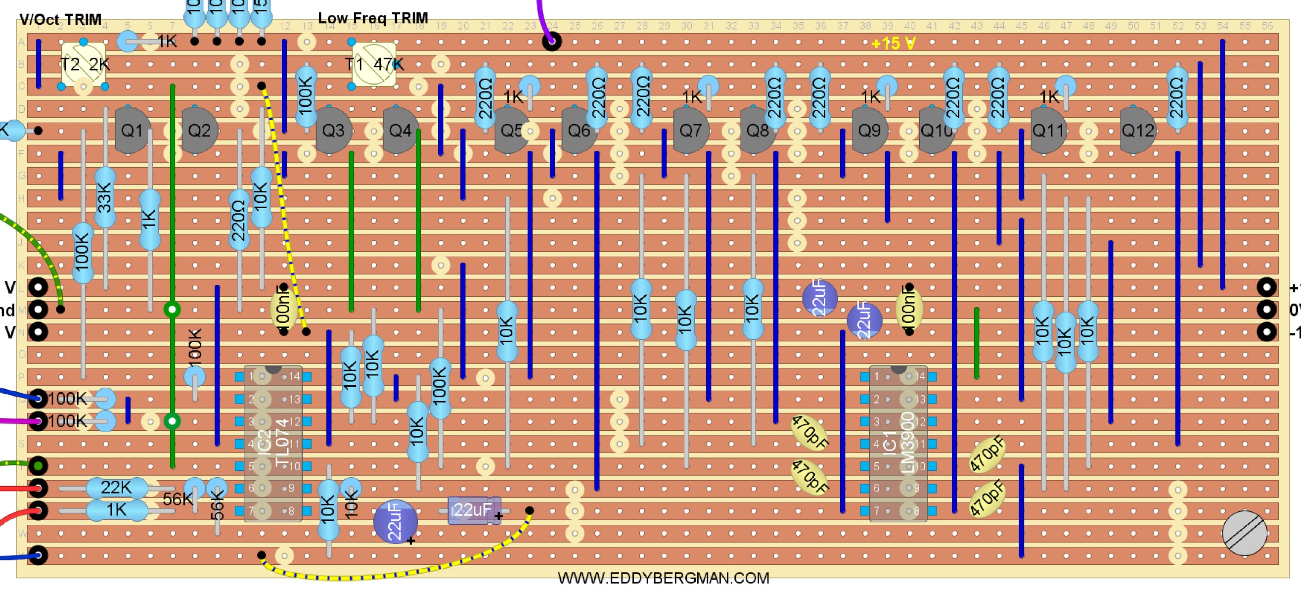
And here's the layout. Like I mentioned before, the layout is verified because it's the one I used for my own build. (All potmeters are shown from the front with shaft facing you). 
Addition: I've had confirmation from multiple readers that this layout has been used successfully. 
To increase the gain I strongly advise to change resistor R41 from 56K to 100K. R41 is the 56K resistor over pins 6 and 7 of IC-2 at the bottom left (from hole U-8 to V-8). Otherwise the volume will be a bit too low.


Stripboard only:


Sometimes you'll see a cut in the copper strip overlapping a component in the layout above. I've done that on purpose so the cuts are easily visible. The layout is pretty complicated especially for beginners because there are so many cuts to be made, so I want things to be as clear as possible. 
Below is the cuts and wirebridges layout. Mark the cuts with a Sharpie or Edding pen on the component side and then put a pin through the marked holes and mark them again on the copper side. Then cut the traces at the marked positions with a sharp hand held 6- or 7mm drill bit.
Cuts and Wirebridges component side:


To make it even easier here's a layout showing just the cuts that need to be made in the copper strips. This is seen from the COPPER SIDE!:


Bill of Materials:


If you don't trust yourself to build this on Stripboard then here's the PCB design for this filter. You can find it on the YuSynth website along with all other necessary information. Click the link below for that.

http://yusynth.net/Modular/EN/ARPVCF/index.html

SOME NOTES ON COMPONENTS:
There are 12 transistors in this filter and they need to be 6 matched pairs. I simply matched them on Hfe value with the transistor tester on my multimeter and that seemed to be good enough because the filter works fine. Officially they need to be matched over the value of Vbe, so if you measure the voltage drop over the Base-Emitter junction, and match them that way, that will be the best method but you'll need to set up a little test rig for that on a piece of stripboard.
Here's the circuit for matching PNP transistors. Use a cut in half DIP8 IC socket to stick the transistors in and easily switch them. You'll need a +/-12V dual voltage source for this setup.
If the transistors are matched the voltage measured between both emitters should be zero (0V).


Make shure you give the transistors time to cool down after you held them between your fingers. I always blow on them to cool them down faster. A match of 0.3 mV or lower is good enough.

The four 470pF capacitors need to be high quality and also closely matched in value. I used polystyrene caps for those. I even matched the 220 Ohm base resistors so they all had the same value. In my case they are all 216 Ohm.  The CV inputs all have 100K resistors on the inputs and a 150K resistor on the wiper of the Cut-Off Frequency potmeter. I didn't have room for them on the stripboard so I hung them over-board so to speak. In reality I soldered those resistors straight to the wipers of the potmeters and in case of the 1V/Oct. straight to the input jack. Then I put some heat-shrink tubing over them and after that I put some heat-shrink tubing over all the wires from one input together so there's never any tension on the resistor itself. This works fine. Of course, if you use a bigger piece of stripboard you can accommodate those resistors on the board itself. Or you can use a small piece of stripboard, solder the resistors on that and connect it to the main board with wires and then use some hot glue and a plastic spacer to glue it to the main stripboard. Lots of options :-)
The resonance potmeter needs to be a dual- aka stereo potmeter. I didn't have one but luckily my neighbour, who repairs audio equipment, had one laying around but it was a logarithmic potmeter. I put it in anyway and it worked like a charm. :) For the trimmer potmeters you can use a 50K for trimmer T1 if you don't have a 47K. In fact, it can be any value from 20K upwards because it's just connected between plus and minus 15V so the actual resistance isn't important for the working of the circuit. But don't forget there is 30 Volts across that trimmer so don't use a value below 20K to keep the current flow down. For trimmer T2 you can use a 2K instead of a 2.2K, but you must keep close to the recommended value for that one because it is part of the input bias for the transistor Q3. I used a 2K on my print and this works fine.

ABOUT TUNING:
This filter has a 1 Volt per octave input connection to make the resonance follow the chromatic scale if you want to use the filter as a sinewave oscillator with resonance fully open. The filter sounds better over all if you use that connection although it is not necessary for the filter to function. There's a trimmer (T2) for the 1V/Oct and the way I set it was to listen to the filter's response while going over the keyboard from low to high. If it is set wrong you'll hear the notes become all muddled up and out of tune at the higher end. If you set the filter potmeters in such a way that it self-oscillates, then the resonance pitch will follow the keyboard scale. So you need to tune the filter so that the self-oscillation is in tune with the keyboard notes if possible. I myself however did not tune it that way. I simply tuned it so the notes sounded ok over all the octaves and left it at that. That's good enough for me and the filter works fine. I don't think the self-oscillation of the filter will track well over multiple octaves anyway, but again, I didn't try that so I may be wrong. The filter is an Alan R. Pearlman design (ARP) and they are usually really good designs. Let me know in the comments if you managed to get self-oscillation tracking over the octaves, please!
The other trimmer is the Low Frequency trim-pot (T1). It needs to be set so that the output wave at the lowest end of the keyboard, and with the Cut-off pot turned all the way counter-clockwise, is a nice sinusoidal bass tone, at least, that is the way I set it. I'm not saying that this the way to do it. I'm simply saying, this is how I did it.
The frequency cut-off potmeter is wired up in such a way that it opens up and lets through the high frequencies when you turn it clockwise and when you turn it counter clockwise it cuts off more and more of the high frequencies making the sound very deep and low.
The values of the potmeters for CV IN and for the audio inputs are not critical and you can use anything from 10K to 1M for those because they are just level potmeters. For the audio potmeters the schematic says to use logarithmic ones but in reality linear will work fine too. It's log because it's audio. Like I mentioned before, I used a logarithmic stereo-potmeter for the Resonance control because that's the only thing I had but it seems to work very well eventhough the schematic says to use a linear type. It probably wouldn't matter what value you use for the Frequency Control either but I'd stick to the recommended 50K or 47K for that one. (I used 100K's for the CV level control potmeters.)
Don't forget to solder the 100K resistors, for the CV inputs, to the wipers of the potmeters or to the input on the stripboard, and don't forget either that the resistor on the wiper of the Frequency Control potmeter is a 150K and not a 100K one! (A mistake I initially made.)

PICTURES AND DEMOs
Here are some pictures of the finished stripboard. This is an early version that has one more jump wire than the new layout. I realized I had a copper strip that was not in use so I used it to replace a jump wire. You can see I marked out the cuts in the copper strips with a black felt pen. I also marked out the 0V/Ground strip with a black line on the component side of the stripboard. Marking out the ground helps to prevent mistakes.


Here's a little video with a demo of what the filter sounds like, taken right after I built it in. Remember when I filmed this it was the first time I played around with this filter so this is just a simple demo of the sounds it produces. At this point in my synthesizer building journey I hadn't even figured out that you need to connect an ADSR to the filter's CV input to get that characteristic filter sound. I just have an LFO connected here. Oh well, I've learned a lot since this was published ^____^


In this second video (which I filmed later) the filter CV-1 input is connected to the little 7555 AD/AR with the big arcade button. This kicks up the cutoff frequency of the ARP filter as soon as a key is pressed and then releases it pretty quickly thereafter. The AD/AR is set to trigger mode so it gives an Attack/Decay response.  The filter is fed with a single squarewave from the VCO. I think you'll agree it sounds amazing. Like a synth should sound. With apologies for my poor keyboard playing :p 
This is a new video posted on the 12th of November 2020:


This filter can also produce those helicopter sounds that you can hear in the beginning of 'Apocalypse Now'. (Francis Ford Coppola had an ARP2600 himself.) All you have to do is turn the cut-off frequency counter clockwise and connect an LFO with a sawtooth wave to the CV input, set to the frequency that the rotor-blades of the helicopter would have and turn the resonance counter-clockwise too. You can add some noise too on Audio IN 2 if necessary.

One little attention point you must remember when using this filter. It's possible to overload this filter with audio in so much that the resonance won't work at full capacity. I had this happen to me where the resonance wouldn't produce the famous whistling sound and I had been trouble shooting for a day changing out the IC's, checking transistors, replacing the capacitors until I finally found out I had the input level set too high (The Audio-1 level potmeter on the front panel). I turned it back by a quarter and everything was back to normal. I'm telling you this so you don't make the same mistake. ^___^

This is what the panel looks like now. I've touched the lettering up a bit because it was all crooked (and it still is I guess, LOL) so it's good enough for me. What's important is what this panel represents; the best friggin' filter I've ever built!! :)


Okay that's it for now.
To finish off this article here's a fantastic documentary about the history of ARP Instruments by YouTuber Alex Ball who has the best synthesizer channel on YouTube in my opinion. Enjoy!


That's it for this article. I hope you liked it.
If you have any questions or remarks please put them in the comments below or on the special Facebook Group for this website.


Sunday, 29 December 2019

Synthesizer Build part-13: THE LFO (MusicFromOuterSpace version).

A very useful, good working and simple to build LFO for square-, sine- and triangle-waves plus a stepless transition between ramp- triangle- and sawtooth waves. A good LFO for beginners to build too. I still use this as my main LFO.

This is the Variable Skew LFO from MusicFromOuterSpace. It doesn't have a sync option but nevertheless it's a very useful LFO and it has been the main LFO in my synthesizer for a long time. It's ideal for all the modulation duties in your modular synthesizer. I was allerted to an alteration that you can make to give this LFO a synchronization mode! That didn't really work for this LFO but more on that later further down the article.
This LFO has the following features: Stepless transition between Sawtooth to Triangle to Rampwave with one potentiometer. Sinewave. Pulsewave with changeable pulsewidth. Frequency control and a switch to go from High to Low frequency setting. 
Frequency Range with switch in 'HI' position = 1 wave every 2,39 seconds to 84 waves per second (239mHz to 84Hz)
Frequency Range with switch in 'LO' position = 1 wave every 7 minutes and 46 seconds to 1,43 waves per second (1,43Hz). The readings you will get will differ a bit from mine due to tolerance fluctuations in capacitor and resistor values.  
Squarewave pulsewidth (or dutycycle) goes from 1% to 99%. The pulse width of the squarewave is set with the same potmeter that controls the shape of the other waves. It also influences the shape of the sinewave. So it can be a bit fiddly to calibrate.
A very feature rich design and a design with very few components so not much can go wrong. It uses a TL084 quad opamp chip and a LM13700 OTA chip.
I even managed to add a little extra of my own design: normally this is a bi-polar LFO meaning all the outputs go from -5 to +5 volt but I added a uni-polar feature with two extra outputs for the saw-triangle-ramp wave and the sinewave that go from 0 to +10 volt. There was room on the circuitboard to put a little TL082 on and make the two inverting buffers with DC offset potmeters. I'm sorry there's no schematic for these additions, I did it from memory, but this feature is included in the stripboard layout. You can take a look at the 8 step sequencer V2.0 schematic which also has an offset feature of my own design and it's the same design as used here. Remember these 0 to +10V signals are inverted, so the waveshape potmeter works the other way around for these waves.
Unipolar LFO's are particularly useful for modulating the pitch of a VCO when you want to set the tuning very accurately.
This LFO is meant to be used with a -12V/0V/+12V powersupply but it works equally well on a -15V/0/+15V powersupply without any changes needed. The overall frequency range will go up a bit with a dual 15V powersupply of course.

LAYOUTS:
Here's the layout, wiring diagram (All potmeters viewed from the front). The layout is verified. I recently built a second one of these LFO's to use as a standalone signal generator and it all worked first time. There's an explanation of the colour-coding of the wirebridges on the layout. If you're wondering why C4 is 10pF instead of 100pF as it is on the schematic, it's a change that Ray Wilson himself made. You can read it in the original text.


(Last revised: 21-Jan.2021 Updated the old layout with some components re-arranged and got rid of a jump wire.  28-Aug.-2021: Cosmetic changes, got rid of resistor colour coding lines. 

Stripboard only:

Cuts and wirebridges seen from COMPONENT SIDE!!


Here's the schematic for the Music From Outer Space LFO. I put in a 100K potmeter for the Wave shape function instead of a 50K as is shown in the schematic. This doesn't make any difference. It'll work the same but put in a 50K if you have one. 
The timing capacitors are C1 and C2 (two 10µF electrolytic caps) switched in series with their negative poles connected together thus forming a 5µF bi-polar cap. This is used for the low frequency setting. The high frequency setting uses just C3, a 100nF capacitor.
Make sure all potmeters are linear types. You can see that only one half of the LM13700 is actually used so it would be easy enough to turn this into a dual LFO. All you need to do is duplicate the LFO circuit and connect it to the pins that lay directly on the opposite side of the 13700 chip. You'll need to make a new layout for that yourself though. A nice exercise in layout making ^___^ 


Bill of Materials. As mentioned earlier, C4 has been changed from 100pF to 10pF by Ray Wilson himself on the MFOS website, so that's why it's 10pF in the B.O.M.:


SYNC OPTION:
There is a circuit design available on the internet that will add a synchronization option to LFO's with a triangle core. I have tried that circuit on this LFO but the timing capacitors in this LFO design are too big for this to work. However it will work on other LFO designs from MFOS. I have linked to the schematics for the sync circuit below so you can check it out. There's also a link to a video by Rich Holmes from Analog Output who shows some changes he made to the circuit to make it work better with his LFO. Very useful to watch if you want to use this circuit with other LFO's.


CALIBRATING the LFO:
Calibrating the circuit should be very straight forward. Connect an oscilloscope to the sinewave output and manipulate the Sine shape trimpot until you get a symmetrical sinewave. Make sure the wave shape potmeter on the face plate is set half way. Turn the symmetry trimmer until the waves look the way they should.
Set the DC offset potmeter so the output reads 0 to 10V peak to peak on those two outputs. That's the bit I added on myself so it's not in the schematic.

Here's a high resolution picture showing oscilloscope screenshots of the different waves.


Here are some pictures of the stripboard with wirebridges and with components:


This is not the board I ended up using. If you look closely you can see the 10pF cap is over pins 6 and 7 instead of 5 and 7 on the left TL084. There may have been more mistakes on it, I can't remember but the layouts are absolutely 100% verified so don't worry about it.


Here's a picture of the panel I made for it. Like I mentioned earlier, it is combined with an AD/AR, the version that uses the 7555 chip. I used multi-coloured LEDs on the outputs to indicate positive and negative cycles of the outputs. There's no practical reason why I did that, I just thought it looked cool. I think every synthesizer module needs at least one LED :)


Please, share and follow this blog and see you on the next one. :)
If you have any questions and/or comments please post them below in the comment section or post them on the  EddyBergman Discussion and Help Facebook group.