A word of warning right at the start; this is an advanced project, not for beginners. You need to know your electronics and you also need to have a good oscilloscope.
The ARP2600 is my favourite synth from the early 70's. It's been used on so many iconic records.
In any synth the filter is the defining factor in the creation of the sound and after tackling the ARP's Envelope Follower I thought it was time to try out the famous 4072 filter. ARP has had a number of well known filter types. The 4012 (4035 for Odyssey) which was a Moog type ladder filter over which they got in trouble with Moog for patent infringement. The 4023 two-pole filter of the early Odyssey synths. Then later came the 4072 (the one we're going to make) for the later ARP2600's. The ones with the orange labels with white lettering. These had a fault at first due to miscalculation, which limited the bandwidth of the filter to below 10kHz. This was later fixed with a few component value changes. And then there's the 4075 which was the filter used in the later ARP Odyssey's.
If you want to build this filter there's really only one schematic you can turn to and that's the Yusynth schematic. So I set to work making a layout. I first tried just starting at the lower left of the schematic and building the layout up from there. Within minutes it turned so complicated I couldn't make heads nor tails of it. So after an other unsuccessful try I came to version 3 of the layout and this time I decided to place all the semiconductor components neatly on the board first. All transistors in a row on top and the two chips in their own space underneath and wire it all up that way. This worked fantastically and after a days work I had a layout that looked really good and, more importantly, turned out to be faultless right from the get go.
I was blown away when I tested the finished filter. Of all the filters I built, from the Moog Ladder Filter to the Steiner-Parker, there is no filter that sounds as good as this one. Now I love the Steiner filter and it sounds awesome but this one just has more quality and better resonance control. More meat on the bone if you know what I mean. It sounds how a synthesizer should sound. But of course this is all a matter of personal perception. Mind you this filter, at least the one I built, has less output volume. It's a bit quieter than other filters which is why I suggested a upgrade of the gain in output opamp. More on that further in the article.
BUILD PROCEDURE
BUILD PROCEDURE
Like I mentioned at the beginning, this is not a project for beginners. It's reasonably complicated and you need to work very methodically and do things in steps. First map out all the cuts in the copper strips with a Sharpy and cut the traces accordingly. Then solder in all the wire bridges and then solder in the components. Keep counting the holes and make sure everything is placed exactly like on the layout, otherwise you will run into trouble with space on the board and things end up not being connected right. I worked from left to right soldering it all in and checking every connection with a powerful loupe. And in the end, of course, it didn't work straight away. It turns out I had forgotten to cut four copper strips near the 1V/Oct trimmer. After I cut those the filter suddenly sprung to life and started making sounds that instantly reminded me of the ARP2600.
SCHEMATIC:
SCHEMATIC:
Here's the Yusynth schematic. It looks a bit weird but the LM3900 really operates on negative voltage, in this circuit.

LAYOUTS:
And here's the layout. Like I mentioned before, the layout is verified because it's the one I used for my own build. (All potmeters are shown from the front with shaft facing you).
Addition: I've had confirmation from multiple readers that this layout has been used successfully.
To increase the gain I strongly advise to change resistor R41 from 56K to 100K. R41 is the 56K resistor over pins 6 and 7 of IC-2 at the bottom left (from hole U-8 to V-8). Otherwise the volume will be a bit too low.


Stripboard only:


To make it even easier here's a layout showing just the cuts that need to be made in the copper strips. This is seen from the COPPER SIDE!:


If you don't trust yourself to build this on Stripboard then here's the PCB design for this filter. You can find it on the YuSynth website along with all other necessary information. Click the link below for that.
http://yusynth.net/Modular/EN/ARPVCF/index.html
SOME NOTES ON COMPONENTS:
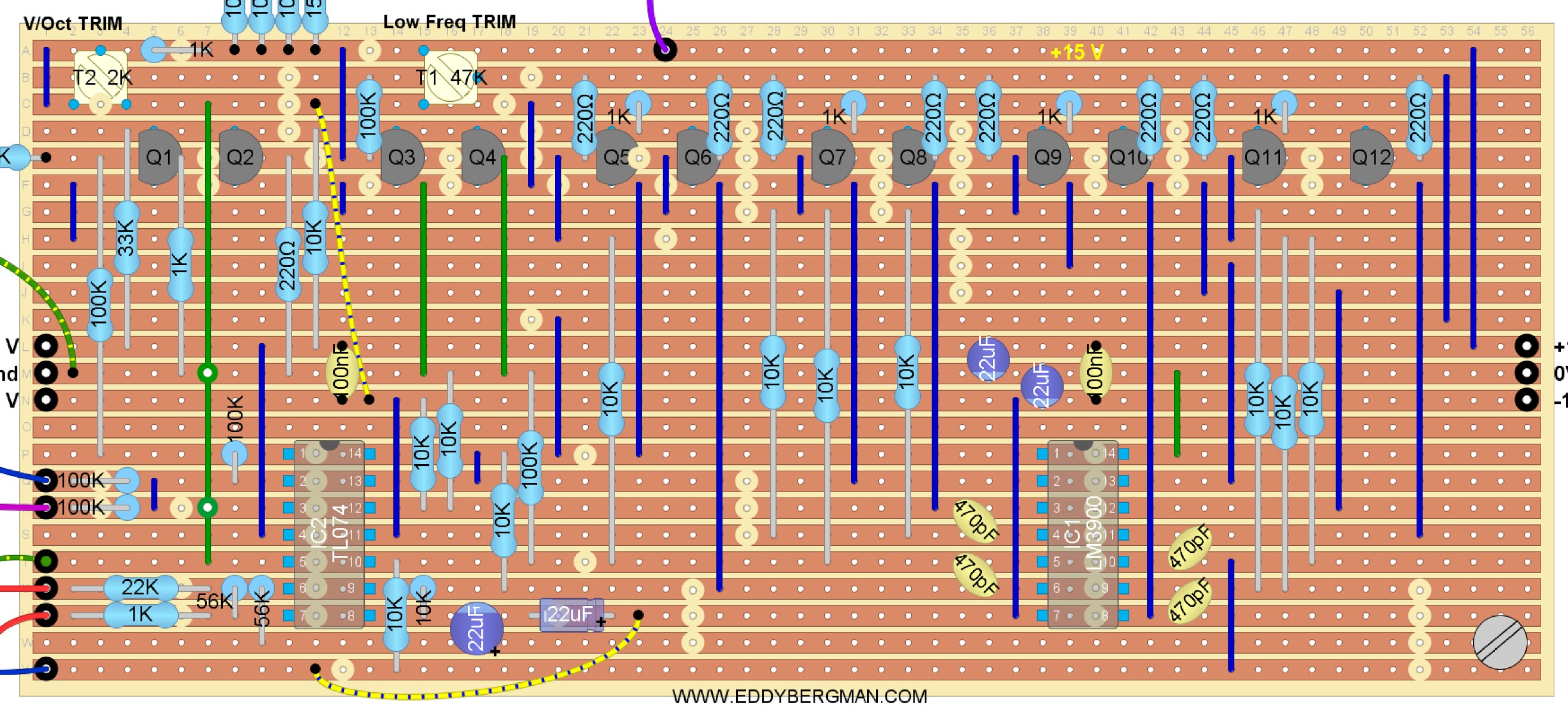
Sometimes you'll see a cut in the copper strip overlapping a component in the layout above. I've done that on purpose so the cuts are easily visible. The layout is pretty complicated especially for beginners because there are so many cuts to be made, so I want things to be as clear as possible.
Below is the cuts and wirebridges layout. Mark the cuts with a Sharpie or Edding pen on the component side and then put a pin through the marked holes and mark them again on the copper side. Then cut the traces at the marked positions with a sharp hand held 6- or 7mm drill bit.Cuts and Wirebridges component side:

To make it even easier here's a layout showing just the cuts that need to be made in the copper strips. This is seen from the COPPER SIDE!:

Bill of Materials:

http://yusynth.net/Modular/EN/ARPVCF/index.html
SOME NOTES ON COMPONENTS:
There are 12 transistors in this filter and they need to be 6 matched pairs. I simply matched them on Hfe value with the transistor tester on my multimeter and that seemed to be good enough because the filter works fine. Officially they need to be matched over the value of Vbe, so if you measure the voltage drop over the Base-Emitter junction, and match them that way, that will be the best method but you'll need to set up a little test rig for that on a piece of stripboard.
Here's the circuit for matching PNP transistors. Use a cut in half DIP8 IC socket to stick the transistors in and easily switch them. You'll need a +/-12V dual voltage source for this setup.
If the transistors are matched the voltage measured between both emitters should be zero (0V).

Make shure you give the transistors time to cool down after you held them between your fingers. I always blow on them to cool them down faster. A match of 0.3 mV or lower is good enough.
The four 470pF capacitors need to be high quality and also closely matched in value. I used polystyrene caps for those. I even matched the 220 Ohm base resistors so they all had the same value. In my case they are all 216 Ohm. The CV inputs all have 100K resistors on the inputs and a 150K resistor on the wiper of the Cut-Off Frequency potmeter. I didn't have room for them on the stripboard so I hung them over-board so to speak. In reality I soldered those resistors straight to the wipers of the potmeters and in case of the 1V/Oct. straight to the input jack. Then I put some heat-shrink tubing over them and after that I put some heat-shrink tubing over all the wires from one input together so there's never any tension on the resistor itself. This works fine. Of course, if you use a bigger piece of stripboard you can accommodate those resistors on the board itself. Or you can use a small piece of stripboard, solder the resistors on that and connect it to the main board with wires and then use some hot glue and a plastic spacer to glue it to the main stripboard. Lots of options :-)
The resonance potmeter needs to be a dual- aka stereo potmeter. I didn't have one but luckily my neighbour, who repairs audio equipment, had one laying around but it was a logarithmic potmeter. I put it in anyway and it worked like a charm. :) For the trimmer potmeters you can use a 50K for trimmer T1 if you don't have a 47K. In fact, it can be any value from 20K upwards because it's just connected between plus and minus 15V so the actual resistance isn't important for the working of the circuit. But don't forget there is 30 Volts across that trimmer so don't use a value below 20K to keep the current flow down. For trimmer T2 you can use a 2K instead of a 2.2K, but you must keep close to the recommended value for that one because it is part of the input bias for the transistor Q3. I used a 2K on my print and this works fine.
The resonance potmeter needs to be a dual- aka stereo potmeter. I didn't have one but luckily my neighbour, who repairs audio equipment, had one laying around but it was a logarithmic potmeter. I put it in anyway and it worked like a charm. :) For the trimmer potmeters you can use a 50K for trimmer T1 if you don't have a 47K. In fact, it can be any value from 20K upwards because it's just connected between plus and minus 15V so the actual resistance isn't important for the working of the circuit. But don't forget there is 30 Volts across that trimmer so don't use a value below 20K to keep the current flow down. For trimmer T2 you can use a 2K instead of a 2.2K, but you must keep close to the recommended value for that one because it is part of the input bias for the transistor Q3. I used a 2K on my print and this works fine.
ABOUT TUNING:
This filter has a 1 Volt per octave input connection to make the resonance follow the chromatic scale if you want to use the filter as a sinewave oscillator with resonance fully open. The filter sounds better over all if you use that connection although it is not necessary for the filter to function. There's a trimmer (T2) for the 1V/Oct and the way I set it was to listen to the filter's response while going over the keyboard from low to high. If it is set wrong you'll hear the notes become all muddled up and out of tune at the higher end. If you set the filter potmeters in such a way that it self-oscillates, then the resonance pitch will follow the keyboard scale. So you need to tune the filter so that the self-oscillation is in tune with the keyboard notes if possible. I myself however did not tune it that way. I simply tuned it so the notes sounded ok over all the octaves and left it at that. That's good enough for me and the filter works fine. I don't think the self-oscillation of the filter will track well over multiple octaves anyway, but again, I didn't try that so I may be wrong. The filter is an Alan R. Pearlman design (ARP) and they are usually really good designs. Let me know in the comments if you managed to get self-oscillation tracking over the octaves, please!
The other trimmer is the Low Frequency trim-pot (T1). It needs to be set so that the output wave at the lowest end of the keyboard, and with the Cut-off pot turned all the way counter-clockwise, is a nice sinusoidal bass tone, at least, that is the way I set it. I'm not saying that this the way to do it. I'm simply saying, this is how I did it.
The frequency cut-off potmeter is wired up in such a way that it opens up and lets through the high frequencies when you turn it clockwise and when you turn it counter clockwise it cuts off more and more of the high frequencies making the sound very deep and low.
The values of the potmeters for CV IN and for the audio inputs are not critical and you can use anything from 10K to 1M for those because they are just level potmeters. For the audio potmeters the schematic says to use logarithmic ones but in reality linear will work fine too. It's log because it's audio. Like I mentioned before, I used a logarithmic stereo-potmeter for the Resonance control because that's the only thing I had but it seems to work very well eventhough the schematic says to use a linear type. It probably wouldn't matter what value you use for the Frequency Control either but I'd stick to the recommended 50K or 47K for that one. (I used 100K's for the CV level control potmeters.)
Don't forget to solder the 100K resistors, for the CV inputs, to the wipers of the potmeters or to the input on the stripboard, and don't forget either that the resistor on the wiper of the Frequency Control potmeter is a 150K and not a 100K one! (A mistake I initially made.)
PICTURES AND DEMOs
This filter has a 1 Volt per octave input connection to make the resonance follow the chromatic scale if you want to use the filter as a sinewave oscillator with resonance fully open. The filter sounds better over all if you use that connection although it is not necessary for the filter to function. There's a trimmer (T2) for the 1V/Oct and the way I set it was to listen to the filter's response while going over the keyboard from low to high. If it is set wrong you'll hear the notes become all muddled up and out of tune at the higher end. If you set the filter potmeters in such a way that it self-oscillates, then the resonance pitch will follow the keyboard scale. So you need to tune the filter so that the self-oscillation is in tune with the keyboard notes if possible. I myself however did not tune it that way. I simply tuned it so the notes sounded ok over all the octaves and left it at that. That's good enough for me and the filter works fine. I don't think the self-oscillation of the filter will track well over multiple octaves anyway, but again, I didn't try that so I may be wrong. The filter is an Alan R. Pearlman design (ARP) and they are usually really good designs. Let me know in the comments if you managed to get self-oscillation tracking over the octaves, please!
The other trimmer is the Low Frequency trim-pot (T1). It needs to be set so that the output wave at the lowest end of the keyboard, and with the Cut-off pot turned all the way counter-clockwise, is a nice sinusoidal bass tone, at least, that is the way I set it. I'm not saying that this the way to do it. I'm simply saying, this is how I did it.
The frequency cut-off potmeter is wired up in such a way that it opens up and lets through the high frequencies when you turn it clockwise and when you turn it counter clockwise it cuts off more and more of the high frequencies making the sound very deep and low.
The values of the potmeters for CV IN and for the audio inputs are not critical and you can use anything from 10K to 1M for those because they are just level potmeters. For the audio potmeters the schematic says to use logarithmic ones but in reality linear will work fine too. It's log because it's audio. Like I mentioned before, I used a logarithmic stereo-potmeter for the Resonance control because that's the only thing I had but it seems to work very well eventhough the schematic says to use a linear type. It probably wouldn't matter what value you use for the Frequency Control either but I'd stick to the recommended 50K or 47K for that one. (I used 100K's for the CV level control potmeters.)
Don't forget to solder the 100K resistors, for the CV inputs, to the wipers of the potmeters or to the input on the stripboard, and don't forget either that the resistor on the wiper of the Frequency Control potmeter is a 150K and not a 100K one! (A mistake I initially made.)
PICTURES AND DEMOs
Here are some pictures of the finished stripboard. This is an early version that has one more jump wire than the new layout. I realized I had a copper strip that was not in use so I used it to replace a jump wire. You can see I marked out the cuts in the copper strips with a black felt pen. I also marked out the 0V/Ground strip with a black line on the component side of the stripboard. Marking out the ground helps to prevent mistakes.


Here's a little video with a demo of what the filter sounds like, taken right after I built it in. Remember when I filmed this it was the first time I played around with this filter so this is just a simple demo of the sounds it produces. At this point in my synthesizer building journey I hadn't even figured out that you need to connect an ADSR to the filter's CV input to get that characteristic filter sound. I just have an LFO connected here. Oh well, I've learned a lot since this was published ^____^
In this second video (which I filmed later) the filter CV-1 input is connected to the little 7555 AD/AR with the big arcade button. This kicks up the cutoff frequency of the ARP filter as soon as a key is pressed and then releases it pretty quickly thereafter. The AD/AR is set to trigger mode so it gives an Attack/Decay response. The filter is fed with a single squarewave from the VCO. I think you'll agree it sounds amazing. Like a synth should sound. With apologies for my poor keyboard playing :p


Here's a little video with a demo of what the filter sounds like, taken right after I built it in. Remember when I filmed this it was the first time I played around with this filter so this is just a simple demo of the sounds it produces. At this point in my synthesizer building journey I hadn't even figured out that you need to connect an ADSR to the filter's CV input to get that characteristic filter sound. I just have an LFO connected here. Oh well, I've learned a lot since this was published ^____^
In this second video (which I filmed later) the filter CV-1 input is connected to the little 7555 AD/AR with the big arcade button. This kicks up the cutoff frequency of the ARP filter as soon as a key is pressed and then releases it pretty quickly thereafter. The AD/AR is set to trigger mode so it gives an Attack/Decay response. The filter is fed with a single squarewave from the VCO. I think you'll agree it sounds amazing. Like a synth should sound. With apologies for my poor keyboard playing :p
This is a new video posted on the 12th of November 2020:
This filter can also produce those helicopter sounds that you can hear in the beginning of 'Apocalypse Now'. (Francis Ford Coppola had an ARP2600 himself.) All you have to do is turn the cut-off frequency counter clockwise and connect an LFO with a sawtooth wave to the CV input, set to the frequency that the rotor-blades of the helicopter would have and turn the resonance counter-clockwise too. You can add some noise too on Audio IN 2 if necessary.
One little attention point you must remember when using this filter. It's possible to overload this filter with audio in so much that the resonance won't work at full capacity. I had this happen to me where the resonance wouldn't produce the famous whistling sound and I had been trouble shooting for a day changing out the IC's, checking transistors, replacing the capacitors until I finally found out I had the input level set too high (The Audio-1 level potmeter on the front panel). I turned it back by a quarter and everything was back to normal. I'm telling you this so you don't make the same mistake. ^___^
This is what the panel looks like now. I've touched the lettering up a bit because it was all crooked (and it still is I guess, LOL) so it's good enough for me. What's important is what this panel represents; the best friggin' filter I've ever built!! :)

Okay that's it for now.
To finish off this article here's a fantastic documentary about the history of ARP Instruments by YouTuber Alex Ball who has the best synthesizer channel on YouTube in my opinion. Enjoy!
That's it for this article. I hope you liked it.
This is what the panel looks like now. I've touched the lettering up a bit because it was all crooked (and it still is I guess, LOL) so it's good enough for me. What's important is what this panel represents; the best friggin' filter I've ever built!! :)

Okay that's it for now.
To finish off this article here's a fantastic documentary about the history of ARP Instruments by YouTuber Alex Ball who has the best synthesizer channel on YouTube in my opinion. Enjoy!
That's it for this article. I hope you liked it.
If you have any questions or remarks please put them in the comments below or on the special Facebook Group for this website.


