Sunday 26 November 2023

Synthesizer Build part-54: JOYSTICK CV Controller (Eurorack)

 An easy to build joystick module that outputs 2 CV voltages to control anything from pitch to filter cutoff and anything else that can be changed with a control voltage.


The finished Joystick module installed in a Nifty Case.

Before I started building my modular synthesizer I had a brief try at flying FPV drones. I bought all the gear and some cool drones but the damn things were way too fast for me to control. This was before the stabilized DJI FPV drones were on the market. Anyway.... I had some gimbals or joysticks left over from my FPV transmitter because I replaced the originals for Hall-effect gimbals, and I always wanted to do a project to make use of one of them. So last week I finally remembered to go looking for a schematic and I found a good one on the Mod Wiggler forum.

Close-up of the circuit:
The image below shows the circuitry for one axis. You need two of these circuits to work both axis of the joystick, left and right [X-axis] and up and down [Y-axis].


HOW THE CIRCUIT WORKS:
It's a very simple circuit. Each of the 2 axis of the joystick is assigned two opamps. The voltage coming of the joystick potmeter goes into the inverting input of an opamp and added to that is voltage from the Zero Point trimmer to make sure the voltage is at zero when the joystick is in the rest position (middle). The gain of the opamp is adjustable with the 1M potmeter marked Range. This determines the maximum voltage you get when you push the joystick fully to one position. This goes from 0 to 10V max. when used with a 12V powersupply.
The CV voltage then goes into a second opamp which has an offset potmeter so we can turn the signal into a unipolar one if we want (all positive or all negative voltage) or just give it some offset or even just to make sure the voltage is zero when the joystick is in the middle position. 
This module is meant for Eurorack (dual 12V powersupply) but it will run just as well on a dual 15V powersupply and if you build it for a Kosmo or 5U synthesizer you have more space on the faceplate to accomodate some extra features.

The joystick I used came out of a Taranis QX7 RC controller/transmitter and it has the following resistance values:
When in the middle position (rest) the resistance is 1,31kΩ. Fully right is 2,15 kΩ and fully left is 550 Ω. Same for the up-down potmeter.
The circuit will take a wide range of joystick resistance values so practically any joystick can be used.
I left the springs installed so the joystick always returns to the middle position when let loose.

Ideas for extra features:
The circuit is very bare bones but you can extend it with, for instance, a momentary switch that cuts the CV voltage if you push it, or one that makes contact if you push it and so outputs an extra gate signal.
An other idea that was suggested to me is to have two input sockets with the voltage connected to the socket switches (normalized) but then you can input an audio signal that cuts the voltage and then the joystick controls the amplitude of the audio thus creating a Manually Controlled Amplifier (MCA).
I'll leave all that up to your imaginations. I didn't have room for extra functions on my panel so I left it as presented here.
I did put in two bi-coloured LEDs to give a visual representation of the voltages on the outputs. It glows red for positive and blue for negative voltages. I connected them straight to the output sockets but with a big 10K current limiting resistor so they only glow at their brightest with the full voltage applied and don't pull down the CV outputs. Also to keep the number of components to a minimum. It works like a charm and looks very cool. Their brightness is a good indicator for the amount of voltage present at the output sockets.  They start glowing at around 2V and then get brighter with higher voltages. I mounted the LEDs above the joystick so they are in full view.
You can use any type of quad opamp for this circuit. I used one of my fake LM324 chips from China and because there are no high frequencies involved it works just fine. You can use a TL074, TL084 etc. They all work fine as long as the pin-outs are the same. It's a good idea to use miniature potmeters for the offset and range controls to save some space on the faceplate. The offset potmeters don't have to be 10K, I used 100K potmeters myself. The range potmeters do need to be 1M otherwise the range of the range will be different ^___^
The trimmers can also be different values. I used 200K trimmers. Afterall they are just voltage dividers in this circuit, so the value is not that important.

CALIBRATING:
The zero point is the point at with the joystick is at rest, right in the middle and in this position the CV outputs must be at zero Volts. You set the zero point with the two multiturn-trimmers.  
The best way to set the zero points for both axis is to have both the Offset and the Range potmeters at the 12 o'clock positions and then connect the CV output to an oscilloscope or volt meter and turn until the voltage is zero. 
Then set the scope or meter to a more sensitive setting and again correct until it reads zero Volts. Try to get it as accurate as you can. After you're done calibrating both channels you don't have to touch the trimmers again. 

Here is the schematic I used for the layouts:


I made a Falstad simulation of the circuit which you can see by clicking here.

Here's one observation I made about this circuit. The voltages from the wipers of the joystick potmeters go through a 51K resistor into an opamp, the gain of which is determined by the 1M potmeter (Range). I noticed that the Range potmeter reaches its maximum at about 1/3rd before the full clockwise position is reached. I think this is due to the 51K resistor. I think it will be better to put in a 91K or even a 100K to get the gain in step with the throw of the potmeter. 
The gain of this stage is determined by the formula: Av = (-Rfeedback/Rin) = (-1M/51K) = -19,6 (the minus simply means the output is inverted). This is too much and that's why the potmeter reaches full gain way before it's turned fully clockwise. With a 100K the gain would be -10 and that would result in the full throw of the potmeter being used. To play it save and make sure you get all the gain you can before you reach the fully clockwise position of the Range potmeter I would suggest using a 91K resistor instead of the 51K on the layout. I've changed the Bill of Materials to include two 91K resistors. However I have not made this change in my own module because I can't access those resistors easily anymore, so I can not guarantee it will fully solve the potmeter throw issue but I can't see why it wouldn't work because the mathematics says it will.
The Falstad simulation doesn't really show this discrepancy so do not rely on it for component values. 

LAYOUTS:
Here is the layout I made for this circuit. It is verified, I used it to build my project. It is small enough to fit flat behind a 14hp Eurorack panel. Beware there are two copper strips underneath the IC that are not cut. They connect the grounded pins together. Pins 3 and 12 and pins 5 and 10. 
There are three 100nF caps visible in the layout but I also put a 100nF cap over pins 6 and 7 of the IC. This is to suppress any voltage spikes or noise. This cap is not visible on the layout and because I had no room for it on the component side I soldered it straight to the pins on the copper side. So there are 4 caps in the Bill of Materials. (I didn't use any bypass caps myself but they are in the layout and B.O.M.).


Here is the stripboard only view. 


Here is the layout for just the cuts and wirebridges. 
As ever mark the cuts at the component side and then stick a pin through the marked holes and mark them again on the copper side. Then you can cut them with a sharp hand held 6 or 7mm dril bit.


And finally here's the bill of materials. It's quite a cheap project if you already have a joystick in stock and anyway, joysticks aren't that expensive if you know where to look. The resistance value of the joystick potmeters isn't that critical. The circuit just uses them as voltage dividers so any value will work. They usually don't go down to zero Ohms. The one I used goes from 550 Ω to 1K3 to 2K15 in the lowest, middle and highest positions.


You can find joysticks on AliExpress for under $20,- for a pair. Just Google: "Radio Rocker Joystick 5K." Those should work just fine.

How to determin which wire is for up and which for down, left or right with a joystick.
Connect an Ohm meter to the middle wire and one of the outer wires of one of the potmeters on the joystick. Say for instance we're looking at the potmeter for the Y-axis (up and down). Now we measure the resistance while moving the joystick up. If the resistance goes down you have the correct wire for the up position. If the resistance goes up that wire should go to the down position on the stripboard, for the Y axis. So if you have the correct wire for a specific direction the resistance between the middle wire and that wire should go down when moving the joystick in that direction, because the wiper of the potmeter moves closer to it. I hope that makes sense.

Here's a screenshot from my oscilloscope. Yellow = X-axis, Blue = Y-axis. In this picture I moved the stick to the outer most positions and you can see both voltages land on exactly 10V maximum with Range turned fully clockwise and no offset applied.


PICTURES:
Here are some pictures I took during the building process:
This is the faceplate I made. Notice the two square holes. I tried fitting two push switches for extra Gate outputs but I came back on that idea because I didn't have enough room to accomodate that.
I made the big round hole with a hand held jig saw.


The finished face-plate with everything installed but without the stripboard. As you can see the knobs are very close together which isn't ideal so when you design your own faceplate for this module take some time to find out the best places to put these potmeters. If you use miniature potmeters you have more room to move them about to find the best placement.


Below is the stripboard with all components mounted except the power connector. The bottom two strips I later cut away go have some more space for the gimbal to move because when I tried to mount the board behind the panel I needed a bit more space. The bottom two copper strips are not used so I could just cut them off.


Here's how I mounted the stripboard behind the panel. I used some plastic tube as a stand-off. If you do the same, drill a few small holes in the sides very near both ends so the glue can run into those and provide a good grip. Then I hot glued that to the back of the panel, making sure the glue flowed around some of the mounting screws for the joystick, for extra grip. Then I hot-glued the stripboard to that stand-off after the wiring up was all done. I had to be careful not to disrupt the movement of the joystick gimbal, keep that in mind when mounting the stripboard behind the panel. There's almost no place to drill a hole through the stripboard for a normal M3 threaded stand-off so this seemed like the best solution. Works fine.


And here's the finished product. Front view:


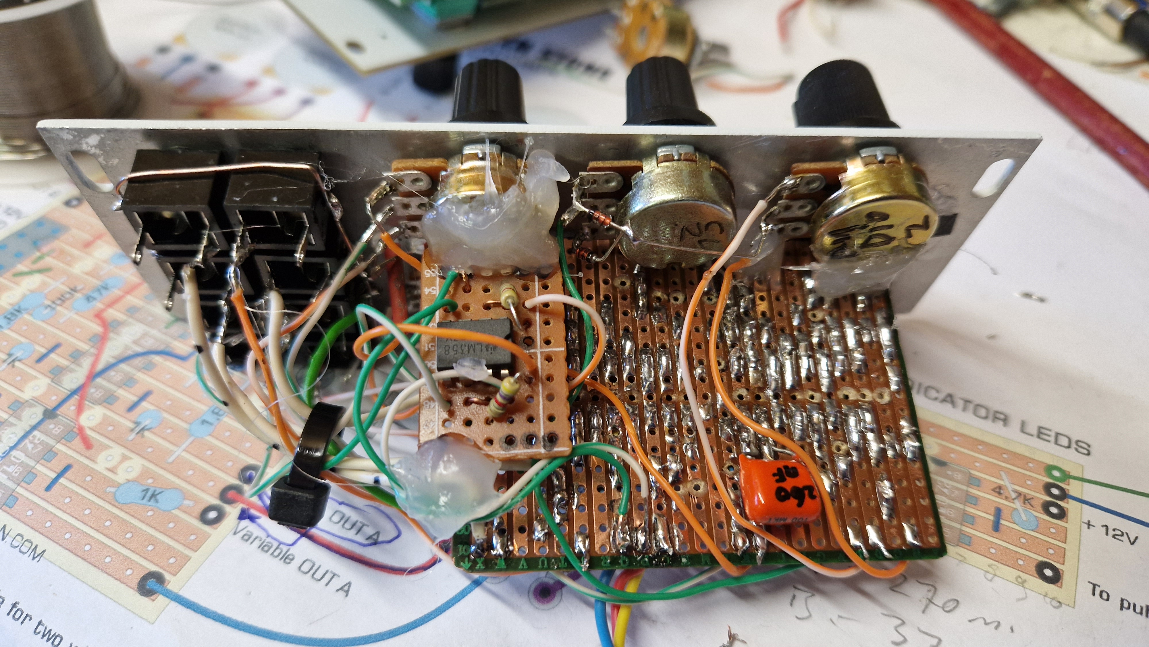
Back side. The depth of the module is just under 4 centimeters. It's 14hp wide (7CM):


Finally a little demo video of the module in action in my 'Nifty Case'. This is just a simple patch I put together in 5 minutes. The X-axis CV is controlling the cutoff of the filter in the Doepfer A-111-6 synthesizer voice and the Y-axis CV is controlling the reverb amount from the FX-Aid.


Okay, that's it for this one. Quite a simple build. The only thing I did wrong was that I forgot that the wipers of the offset potmeters connect to the inverting inputs of the opamps so I had the offset potmeters wired the wrong way around. An easy fix. This is a very easy to build module and, I think, a very useful one especially for live performing. It's in fact the equivalent of a synthesizers modulation- and pitch-bend wheels all in one.

If you have any questions or remarks please put them in the comments below or in the special Facebook group for this website.

If you like these free projects and you would like to support the website you can buy me a coffee, there's a button for that underneath the main menu. You can also use this Paypal Me link which cuts out the middle man. All donations go straight back into new projects and the upkeep of this website. Thank you!!


Tuesday 6 June 2023

Synthesizer Build part-53: RINGMODULATOR with AD633 for Eurorack.

This is the MFOS Ring-Modulator based on the AD633 analog multiplier chip and it sounds awesome. It's very small and will easily fit a Eurorack system so naturally no problem for a Kosmo system either. This ring-modulator is perfect for creating bell sounds and all sorts of timbres.

This is the first article in which I did not actually build the project myself. I was asked by one of our Facebook members, Justin Andrews, to make a stripboard layout for a schematic that he found. It sounded like an ideal little project for the website so I set out to make the layout. Justin built it up and it worked like a charm first go. The AD633 is a small DIP 8 Analog Multiplier chip and they can be a bit pricey. They cost about €22,- each. The MFOS article states they are cheap but they seem to have gone up in price. Make sure you get them from a reputable source though, not from AliExpress for a few dollars. Those will be 100% fakes! I looked around and it seems they are no longer in production but there are still electronics webshops who have them in stock so they shouldn't be hard to find.
The other chip in this circuit is a single opamp, the LF411. I don't know why this type was chosen over the normal µA741 and I suppose you can use a 741 if you wish. The pinout is the same. Only the actual opamp connections of the chip are used not the offset controls. The 43K resistor is a bit of a strange value. You can get away with a 47K too I reckon. Not even the 2,2µF input caps need to be specifically that value. They are DC blockers and in that function you can use 1µF upto 4,7µF without any problems. Together with the 100K resistors these caps form a highpass filter with a cutoff frequency of 1.6Hz if you use 1µF for the caps. It's even lower with higher values so no influence on the sound what so ever whatever value cap you use.
Here is the link to the full article on the Music From Outer Space website.

SCHEMATIC.
Here's the schematic for this project. As you can see it can hardly be simpler and there are no trimmers to set so no calibration necessary. If you read the article linked above you'll see that right at the top Ray Wilson says not to build this project as it has been superseded by newer ones but that doesn't mean this design doesn't work of course. Far from it in fact. It works very well. It's just very basic in its setup.
Both inputs, the Carrier and the Modulation input, are AC inputs. They have an electrolytic capacitor in series with the inputs so this ring modulator is only for audio range signals, not for CV. In the MFOS article it is stated in the Bill of Materials that these should be ceramic capacitors so in fact bi-polar, but I would just put in electrolytic capacitors. That always seems to work just fine and they are used in many other projects for the same function without any problems.


The circuit has two settings: Modulate and Multiply. Justin's experience was that the Multiply mode had a more choppy sound with more artifacts and harmonics. You can see in the scope screenshots at the bottom of the article why that is.
The circuit needs signal at synthesizer levels to work well. The input is meant for 10Vpeak-to-peak signals so if you want to use it for lower level signal you are advised to amplify those first to at least a few Vpp before they enter the ring modulator. 
The circuit is designed to run on +/-12V but I don't see why it wouldn't run normally on +/-15V either.

There is an updated version of this ringmodulator called the Sonic Multiplier which is more difficult to build and has a quad opamp in it and uses an internal sinewave generator with an LM13700. I have not made layouts for it but here is the link to that project on the MFOS website:

LAYOUTS:
Here are the layouts I made for this project and they have been verified. Beware the size of the stripboard is only 16 strips by 26 holes. I see I made one little oversight in the layout design. It would have been better if I had put the power connector at the bottom instead of at the same side where the faceplate is meant to go. But it still works fine of course :) 
Beware the negative 12 Volt is the top connection and the positive 12 Volt is bottom connection of the power header.
Wiring diagram:


Stripboard only view:


Below are the cuts and wirebridges as seen from the COMPONENT SIDE! As always, mark the cuts on the component side and then stick a pin through the marked holes and mark them again on the copper side. Then you can cut them with a sharp hand held 6 or 7mm drill bit.


Bill of Materials. I typed this bill of materials in Notepad so it's a bit small:


PICTURES.
Here are some pictures of Justin's work. He did a great job and made a really cool faceplate for it too, in Eurorack size. 


The finished module. Justin used waterslide decals for the faceplate artwork and sealed it in with a coat of clear lacquer:


Oscilloscope screenshots:
Here are some scope screenshot combining different waveforms in both Modulation and Multiplication Mode so you can see the difference in processing. I put multiple images together in one to save some space.


DEMO VIDEO.
And finally a demonstration of the ring modulator in action.


So that's all for this article. Not much of a write up but then again there's not really much more to say about this Ring Modulator. It does its job and it does it very well. If you have any questions or remarks you can put them in the comments below or post them in the special Facebook Group for this website.

If you enjoy these projects and would like to help with future projects and the upkeep of the website, you can buy me a coffee. There's a button for that underneath the main menu if you're on a PC or Mac. Otherwise you can use this PayPal ME link for a small donation. All donations go straight into new projects and website expenses. Thank you!

Sunday 26 March 2023

Synthesizer Build part-52: 4 CHANNEL FEEDBACK EQ/DISTORTION (Monotropa) Eurorack.

A 4 channel feedback equalizer / distortion module that will fit a Eurorack system. 

I came across this circuit in a post on the LookMumNoComputer forum. Bpbby posted a Falstad simulation of this circuit and it intrigued me because I never heard of it before. He found the circuit on this website: www.reverselandfill.org

It's a pretty cool circuit. Simple too. We have 4 filters, each covering a part of the audio range, and then there's a feedback loop that connects the output back to the input. The circuit is called the Monotropa, which is the name of a plant. Don't ask me why. I don't see any logic in that. ^___^
Here's the schematic of this circuit:

Here is the Falstad simulation of this circuit:

LAYOUTS:
Here are the layouts I made for this project. They are verified as always. I built it for my Eurorack case but you can just as easy make this for a Kosmo sized synthesizer. I that case you could even build the 7 channel version because you'd have more space on the panel for the extra potmeters. Yes there is a 7 channel version of this circuit but you'd have to Google that. This article deals with the 4 channel version. This circuit is designed for +/-12V but I can't see why it wouldn't run equally well on a +/-15V powersupply.

Here's the wiring diagram. For the first time in the history of this website I show the potmeters from the back side! I should have done that all along because it's easier with wiring up the panel but there it is. I started out showing potmeters from the front in my layouts and for the sake of consistency I stuck with that, upto now. I had to connect some components straight to the potmeters and audio jacks to save space on the stripboard:


Below is the stripboard only view. The stripboard is small enough to mount parallel with the front panel behind the potmeters and sockets. You could drill a hole through the lower two strips which are not in use and use a standoff to mount it to the front panel. The wiring will also act as a stabilizing feature. I just used some plastic tube and hot-glued them to the back of the potmeters and to the copper side of the stripboard. That's secure enough. I soldered the powerconnector straight to the stripboard without using pinheaders and sockets. That way you only have 3 thin wires coming from the board with a Eurorack connector (female) on the other side to plug it in. If you want to use bypass/de-coupling caps there's room enough to solder those in over the powerrails and add some 10µF electrolytic caps if you want extra stabilization of the power supply voltage. These components are not in the layouts and are not listed in the Bill of Materials!


The Cuts and wirebridges as seen from the COMPONENT SIDE!!


Here's the Bill of Materials:


PICTURES:
Here's a look at the finished product:


Here are some screenshots from the oscilloscope showing the influence of the feedback on the output signal: 


And finally a little DEMO video I made. I built my version with 100K potmeters because that's all I had and consequently it doesn't sound as good as it could be with 10K pots. I assure you though, it is worth building but keep to the component values in the layout and schematics. Some potmeters are more effective than others depending on the frequencies that are put through this circuit because this is of course an equalizer. So a Low Frequency potmeter isn't going to have much effect on a high frequency bit of audio that's put through it. In the video I have it connected to a 555 VCO that is fed by the Sample and Hold of the previous project.


There's a useful tip in the comments below suggesting to use this EQ with a squarewave and then play with the Pulse Width Modulation of the squarewave in combination with the feedback of the EQ. That should sound pretty awesome!

Okay that's it for now. Not much of a write up I admit but real life issues got in the way. I might revisit this article later and expand on it. I hope you understand and don't mind. For now I just wanted to give you all the necessary layouts etc. to build this Feedback Equalizer. I already heard from one person who built it and he's very happy with it. If you have any questions please put them in the comments below or on the special Facebook Group for this website.

If you find these projects helpful and would like to support the website and its upkeep then you can buy me a Coffee. There's a button for that underneath the menu if you're on a PC or Mac. Or you can use this PayPal.Me link to donate directly. All donations go towards the website and projects. Thank you!

Friday 10 March 2023

Synthesizer Build part-51: SAMPLE & HOLD new version.

A revised version of the earlier 'Yet Another Sample and Hold' (YASH by Rene Schmitz) project.

This is the same core S&H circuit as the earlier one I published. That was one of the first projects I built and that was just over 3 years ago so it was time to update it. The things I added on myself were put together rather clumsily, especially the x1/x0.5 CV range switch that I put in. (The previous version works fine, don't get me wrong.) I have now replaced that range switch with a range potmeter so you can set the range to any level you want. The toggle switch for external or internal input has also been removed and instead I used the internal switch inside the External Clock input socket.
If you built the previous version then it should be quite easy to just replace the stripboard with this new version. You will have to make room for the extra Range potmeter but there will be a hole left over from the range switch so maybe you can drill out that hole to 7mm and use that for the potmeter.

SCHEMATIC:
Below here is the schematic drawing I made in Photoshop of this sample and hold circuit. It has the offset opamps and attenuation I designed added on, connected to the output of the LF398 Sample & Hold chip. The offset potmeter is a 100K linear type. You could use other values but that will alter the range a bit so I'd stick with the 100K. The Attenuation potmeter however must be a 100K one because it determins the gain factor of the opamp. If you put in a 1M for instance it won't only attenuate but also amplify which you absolutely don't want because the CV voltage will get way too high and it'll sound really bad connected to a VCO, if you get sound at all. There's a 470 Ohm resistor in series with the attenuation potmeter to make sure it doesn't go all the way down to zero and you'll always get a little bit of a signal.  (I suppose you could get away with using an other value for the Range potmeter as long as the resistor between pins 2 and 7 is the same value as the potmeter. Then the balance (or ratio) between the two stays the same.)
Now, I know you are not really supposed to use an inverting amplifier with a feedback resistance that is lower than the input resistance. Normally Rf must be bigger than Rinput otherwise the opamp could draw too much current. I have however done some measurements and in this case it is absolutly fine. I used an NE5532 dual opamp in my circuit and the current always stays below 15mA.
The Offset control is included in the circuit so you can transpose the whole CV output up or down by as much as you like. This is handy if some of the notes produced are below the 0V line. In the normal case you would just hear a C0 note for those but if you give the CV an overall higher offset then all those notes will be audible. If you use the S&H to modulate a filter those negative voltages could sound really good so in that case you can dial in the effect you want to achieve with the offset control.
I put a 470pF capacitor over the output opamp because with testing I noticed a lot of little voltage spikes on the signal when I viewed it on the oscilloscope. The capacitor turned out to be a very good solution to suppress those little voltage spikes.
The Sample Rate potmeter needs to be a 1M Ohm linear type. I didn't have one so I used a 500K potmeter and that also works perfectly fine. Don't use any value lower than that though otherwise your frequency range will be very limited.
If you build this project and you find you can hear the pulse train in other modules, coming in over the power rails, then try putting a big electrolytic capacitor over the powerrails of this S&H module. Something like a 470µF or 680µF over the plus and the ground should do the trick. That should be enough but if the problem persists then also put one over the negative rail.
This circuit works equally well on +/-12V as on +/-15V. The current draw of the circuit is about +15mA for the positive rail and 10mA for the negative rail maximum.


THE SCHEMATIC EXPLAINED:
The Schmitt-Trigger [A] at the bottom left is wired up as a Low Frequency Squarewave Oscillator and produces the clock pulse with the potmeter controlling the frequency. The clock pulse then goes to the switch connection of the external clock input socket. If there's no cable connected, the signal goes through the switch to the base of the transistor. Now when the clockpulse is high, it makes the transistor conduct and so the plus 15 Volt coming in over the LED is now connected to ground. The LED lights up and the voltage at the collector is practically zero (except for the voltage drop over the transistor) so the transistor actually inverts the clock pulse at this point. Then the pulse goes through a Schmitt Trigger inverter to invert it back to normal and then through a 470pF capacitor which changes the pulse (or actually squarewave signal) into a trigger signal. It then goes through two other inverters to cut off the negative part of the trigger pulse (a squarewave always produces a positive and negative trigger pulse, from the rising and falling slope of the squarewave, if it goes through a capacitor) to end up with the same positive phase it had at the beginning. It now goes into pin 8 of the LF398 and triggers it to take a sample of the voltage on pin 3. It presents this sample at pin 5 from where it goes into the two opamps to be buffered and more. At the first opamp we can introduce an offset voltage that will shift the whole pulse train up or down in voltage without changing the voltage difference between the pulses. In other words the offset voltage is just added (when positive) or subtracted (when negative) from the pulse train. Because this offset voltage goes into the inverting pin of the second opamp (summed with the pulse train) the working of this offset voltage is actually inverted but this just means the positive voltage needs to be connected to the counter clockwise side and the negative voltage to the clockwise part of the offset potmeter. The pulse train is inverted back to normal in the second opamp. At the second opamp we have a variable gain potmeter which has a maximum resistance which is the same as the input resistor which means the gain can not increase, only decrease. With this we can set the maximum voltage difference between the highest pulse and the lowest pulse generated. This then determins the range of the pulse train. So the pulses can for instance all be between zero and 1 Volt (one octave) or between zero and 7 Volt (7 octaves) and anything inbetween. This can give the pulses a more musical sound. There's a 470 Ohm resistor in series with the potmeter to make sure the gain can never be zero and we always hear a signal. The 470pF capacitor is there to suppress any voltage spikes on the output CV.

LAYOUTS:
Here are the layouts I made for this project. I used these layouts for my own build so they are verified as always. Make sure you copy them accurately and it'll work first time.
Please keep in mind that the LED is a vital part of the circuit so don't leave it out! It's best to use a normal red, green or yellow LED for this either 3mm or 5mm. 
This is the wiring diagram:


The Offset and Output Range options are of my own design. The Output Range is particularly useful. It determins the range between the lowest and the highest possible notes you will hear. You can set it so all the random CV Voltages (or notes) fall in the same octave or higher, upto a range of over 7 octaves. The inclusion of this option saves you from having to put the S&H output through an external attenuator to achieve this effect.

Here is the stripboard only view:


Here's an overview of the wirebridges and the cuts that need to be made in the stripboard as seen from the COMPONENT SIDE!
As always, mark the cuts on the component side and then stick a pin through the marked holes and mark them again on the copper side and then cut with a sharp, hand held, 6 or 7mm dril bit.


Here's the Bill of Materials:


OSCILLOSCOPE SCREENSHOTS:
Here are some screenshots from the scope:

In the shot below you can see the little voltage spikes I was getting when I first tested this circuit. They are the thin overshoots on the rising and falling edges and they also appeared in between in some cases.


Here's the result after I put in the 470pF capacitor over the output opamp. Nice clean CV output:


With all these images I used a sawtooth wave as 'Signal to be sampled', not noise. You can still get sort of random notes even without using noise on the input if the sample rate differs enough from the frequency of the wave you're using. However the paterns will be repeating, they won't be totally random, which can be good for creating melody or bass lines. 
Here's a sawtooth wave being sampled at a very high rate:


In the picture below you can see that the original wave being sampled was a sawtooth wave. Fast rise and slow decline. The CV voltages all lie in one octave (0 to 1 Volt) because the range potmeter was set almost fully counterclockwise. This picture was also taken before I put in the 470pF capacitor so it shows the voltage spikes too.


PICTURES:
Here are some pictures I took while I was building this project:
The cuts and wirebridges ready:


Below you can see the components mounted except for the IC's. Note the vintage Polystyrene 1nF timing cap I used at the top right. It has a red stripe on it. That doesn't mean it's polarized. The stripe indicates which of the legs is connected to the outer layer of aluminium in the capacitor. That leg should always go to ground (or the lowest voltage potential). That way it acts as shielding to prevent hum. Now, if you have a cap that isn't marked but you want to find out which leg is connected to the outer layer and you have an oscilloscope then connect the probe to the capacitor; ground to one leg and probe tip to the other leg. Set the scope so it's quite sensitive and touch the capacitor body with your fingers. Now you become the signal source just by touching the capacitor body (not the legs). If you get a pronounced waveform on the scope then your probe tip is connected to the outer layer and the ground clip is connected to the inner layer. If you reverse them and touch the capacitor body again, you should get little to no deflection. Now you know the leg that outputs the biggest signal is connected to the outer layer and this leg should go to ground. However it is not necessary to do this procedure. I just wanted to tell you how you can find this out, but the capacitor will work fine which ever way you put it in because it's not polarized and this circuit is not that sensitive to hum.


The finished stripboard. I used the old Sample and Hold faceplate and soldered the new stripboard to the old wiring. This particular faceplate I made is a bit of a weird shape because of how I built my synthesizer. It actually sits in a little wooden plank above the other modules. You could say it's sort of a 1U module but for the Kosmo format :)


VIDEO DEMO:
I made a short video demo of the sample and hold in action. The S&H is connected to a Thomas Henry VCO. The input is white noise from the 5 sorts of noise module. The audio goes through the Steiner Parker filter and boy does it sound good!!


Finally I want to leave you with an excellent video by the 'Monotrail Tech Talk' YouTube channel which explains all the different things you can do with a Sample and Hold and discusses some awesome patches. Subscribe to him while you're there. It's an excellent channel for anyone into modular synthesis.   


That's it for another one. If you have any questions please put them in the comments below of post them on the special Facebook Group for this website.

If you find these projects helpful and would like to support the website and its upkeep then you can buy me a Coffee. There's a button for that underneath the menu if you're on a PC or Mac. Or you can use this PayPal.Me link to donate directly. All donations go towards the website and projects. Thank you!

Friday 10 February 2023

Synthesizer Build part-50: UTILITY LFO for EURORACK

This is the Ken Stone Utility LFO, the bigger version of project 47 with an extra feature that I added. I managed to make the stripboard even smaller than the 'Simple Dual LFO' so it fits even the 'Nifty Case' Eurorack skiff. The LFO has the following waveforms: Pulse, Square, Saw to Triangle to Rampwave and a Variable output which has a mix between Square and Triangle/Saw/Ramp waves. I later added a mini-mixer that adds the two variable outputs together to get even weirder waveforms.

An other LFO might not be the most exciting of projects but I think this LFO will be worth it because of the weird waveforms it can make and because I realized, now that I have my own Eurorack system, that modulation sources are important to have. To quote a popular YouTuber: Modulation is what makes Eurorack interesting. I even added a feature of my own later on. It's the ability to mix both variable outputs together to get a variable A+B output. That's at the bottom of this article.
The Dual LFO from project 47 is just the first two stages of the Utility LFO without the mixing stage. Because I actually use the Dual mixer in my Eurorack setup and I loved the idea of having the full Utility LFO available, I thought I'd build the whole LFO this time and try and make it as small as possible. It is 49mm deep and the panel is 9HP wide (4.5 centimeter). This is a bi-polar LFO meaning the waveforms go both positive and negative in voltage.
This LFO does not have a sync option but this is a really useful LFO for a Eurorack system because it has not only the normal waveforms you'd expect but the option to merge waveforms together which makes for some very weird modulation possibilities. And because this is a Dual LFO you could mix the 2 variable waveform outputs together in a Multiple and make even weirder shaped waveforms. That mixing needs to be done outside of this module though. I couldn't fit that inside this design. This LFO would pair really well with the Dual Voltage Processor for that reason.
I managed to get everything on an 18 by 24 hole wide piece of stripboard. Six potmeters and eight output sockets on the panel, and an extra little print for the two bi-colour rate indicator LEDs which I made separate from the main print just like on the Dual LFO and as mentioned before a second little print to mix the two variable outputs together. The panel I made for it is 9 HP wide (4.5 centimeter). You might be able to make it even smaller if you use smaller potmeters in the panel. Even though I included an L-Bracket in the layout, I didn't use one. The stripboard is actually hot-glued in place in between the two columns of potmeters straight to the back of the panel making sure no copper strips make contact with the metal of the panel. I did this to keep the overall depth of the module as low as possible.
I did not include a Eurorack power connector on the print although there is room enough left to put one in. Instead I made a powercord with a Eurorack connector at the end so it always stays connected to the stripboard. This is handier because eurorack ribbon cables take up space too and this is a smaller footprint solution with only three thin wires.
This is mainly a Eurorack project but naturally this circuit will work just as well in a Kosmo sized synthesizer. I optimized the circuit to run on +/-12V but it was originally intended to be run on +/-15V. You will get higher amplitude waveforms when you run this on a dual 15V powersupply so if that's a problem for you, you can change the 1K8 resistors I used on the waveform outputs back to the 1K's you see in the schematic. The original schematic uses +/-15V.

SCHEMATIC:
Below is the schematic I used for my layout. I put in bigger timing capacitors because I wanted one LFO running really slow and the other to about 20Hz. That is more useful for my modulation needs but you might want different values so I strongly advise you to do some testing with different capacitor values to get the LFO in the frequency range you desire.
The types of quad opamps and the one dual opamp used in this project are not critical. The schematic calls for TL074 and TL072 opamps but you can use anything with the same pinout. I used two LM324's and an NE5532 dual opamp. Btw, I did not include the transistor with the rate LED as seen on the schematic but I designed my own circuit for that so I could use bi-coloured LED's. It's just two opamp voltage followers (or buffers) feeding the LED's with the signal from the Pulse output. You can connect them to any output you wish but the pulse is the clearest for the LED's.
Here's the schematic drawing. Beware the opamp numbering does not follow the opamp order I used in the layout.
  

LAYOUTS:
Below are the layouts I made for this project. As ever they are verified. I used them for my build. I changed the order of the opamps used from the order on the schematic. I setup one LFO using all the opamps on the left hand side and the other LFO using all the opamps on the righthand side of the IC's on the stripboard. That made it more compact plus easier to keep the overview. Luckily I did not need to make any changes or do any troubleshooting. I built it and tested it and everything worked first go.
You need four 100K and two 500K linear panel potmeters to this project. Measure and test them before you use them. That can save you some troubleshooting later. If you plan on mounting the stripboard to the panel with hot-glue like I did then try to solder the hook-up wires of the righthand side (the side that's glued to the front panel) as far to the middle as possible so you can still get to them once the stripboard is glued in place. This won't be possible with all wires but try. You could also solder them straight to the back/copper side.
Wiring diagram:


Stripboard only view:

Here are the cuts and wirebridges as seen from the component side! As always, I advise to mark the cuts on the component side first with a black waterproof marker pen and then put a pin through the marked holes and mark them again on the copper side. Then you can make the cuts accurately and you can see where the cuts are when you're soldering in the components.


Bill of materials. 
The timing capacitors listed were chosen for my specific needs. I advise you to go by the schematic (47nF) or else test and determine the best values for your needs. You can use the Falstad simulation linked at the bottom of the article to test different values before building.
No bypass caps are included in this BOM because I didn't use any. They are on the schematic and you can put 100nF caps over the power connections on the IC's to ground if you want to. To do all IC's you'd need six 100nF ceramic caps (you don't have to do the LED driver IC).
This BOM does not include the components for the little mixer I added on further down the article. For that you will need 4 x 100K resistors, a 1K resistor and a 200K trimpot and a TL072 dual opamp.


PICTURES:
Here are some pictures of the build proces and the panel I made for it. I had some fill-in panels left from when I bought my 'Nifty Case' Eurorack case and I used one of them to make my front panel. It was already cut to the right height so ideal for this project ^___^  All I had to do was cut off a piece that was 4.5cm wide (9HP) and spray paint it. I labeled everything with an Edding 400 marker pen.

Wirebridges and cuts. I made some minor changes to the layout after I built this so there are a few discrepancies between this picture and the current layout.


Stripboard ready for testing side A:

Panel, not yet labelled:

The finished module with the little 10 by 6 hole stripboard for the rate indicator LED's glued to the back of one of the potmeters. If you look closely at the sockets you can see I soldered all ground connections together with one copperwire going round them all. A wire goes from there to the ground connection on the stripboard.


The finished product:


Here's a little demo video I made showing the LFO in action in a little Eurorack setup. You can hear how the 'Pico Voice' VCO changes in sound as I connect the LFO to it. But then I get distracted by the Pico DSP effects module and the 2hp Freez, LOL. Oh well. You can hear the difference it makes anyway :)


(As you may have noticed, I really suck at making demo videos, LOL)

WAVEFORMS:
Here are some screenshots from the oscilloscope showing some of the waveforms. The one below shows the sharpest a sawtooth wave you can get. Pretty fast rise!


Cursor readings at LFO-B squarewave output:


Here is a collection of variable output readings from Variable output B:


To give you an idea of what can be achieved by mixing the two variable outputs in a simple passive multiple, here are eight images I put together to give you an impression. This should sound awesome with very slow running LFO's which is why I soldered a few more caps in parallel over the timing cap of LFO-B.


You can imagine that some of these waveforms, when put through a quantizer, would generate awesome melody- or bass-lines that can be easily manipulated with the LFO parameters. I tried to capture a little of that in the demo video I posted below.

Here's some technical data from the LFO:
LFO A: freq. range: 270mHz to 24Hz. 
LFO B: freq. range.: 41mHz (one full cycle every 24 seconds using a 650nF cap) to 2Hz.
Duty cycle of the pulsewave output goes between 2% and 98%. I made a mistake and used a 100K potmeter for the Shape but it needs a 500K potmeter. I only had one 500K pot so I put it in LFO B and the screenschots above are from that LFO. You can use a 100K for shape but that will significantly lower the range of the duty cycle (20 to 80%) also the slope of the Saw-/Rampwaves will be slower rising. It will also speed up the overall frequency of the LFO.
Maximum current draw = 20mA for both the positive and negative side.
The maximum amplitude of the waveforms is about +/-5V except for the Variable waveform output. When that potmeter is set to the mid point the output amplitude drops to about +/-2.5V because the potmeter acts as a voltage divider so in the mid position the amplitude is half of what it is when it is fully clockwise or counter clockwise. (We effectively have two 50K resistors on either side of the wiper of the 100K potmeter.) These may seem like low voltages but keep in mind that an LFO is usually attenuated anyway because if the changes are too big it just doesn't sound good on a VCO or in most patches. If you really need higher voltages you can make the 1K8 resistors on the outputs even bigger.

Here's the link to the Falstad simulation of this circuit. This is the Dual version with one speed potmeter at 100K and the other at 500K as it is in my LFO. You can change these variables by right clicking on them and choosing 'Edit':

EXTRA FEATURE:
Okay as I write this it is four days since I posted this article and the cool looking results from the mixed variable outputs kept going through my mind. I really wanted to incorporate that into this design and now I found a way. I used an other small piece of stripboard on which I soldered a dual opamp and wired it up like the mixer in article 17 with 2 inputs. I knew there was no way to put an extra output socket on my panel so I sacrificed the squarewave output of LFO-B. That was the least useful of the outputs because I can get a squarewave anyway from the pulse output if I need one and I still have the squarewave of LFO-A. So I carefully soldered in the little mixer print which was just as big as the little LED driver and wired it all up and I re-labelled Square output B into 'Vari A+B'. I used a 200K trimmer to go over the inverting input of the second opamp and the output so I could adjust the gain and make it a little higher than the Variable outputs. I placed the little print above the sockets and used hot-glue to stick it in place. It is actually glued to the little LED driver board. This works perfectly! Now I have an output with two variable waveforms mixed together coming out of it.
Here is a picture showing how I added the mixer. I used two rigid copper wires to tap the signals from the sockets and lead them into the mixer. The non-inverting inputs of the opamps are connected to ground on the copper side:


Here's the layout of this little mixer. Mine is even smaller than this layout, but this will work fine. All resistors are 100K:

Here's the schematic for this little mixer:


DEMO VIDEO:
Finally I want to show you a little experiment I did using the new output. I put the Variable A+B signal through a quantizer (the 2hp Tune) and from there into the Pico Voice Wavetable Oscillator. The audio then went through the Pico DSP for some added reverb. You can really generate the weirdest melodies with this although this setup would benefit from the Voltage Processor because the negative phase of the signal does not produce any notes so it needs a positive offset voltage and the signal can do with some attenuation to get the notes closer together but I think you get the idea watching this short demo:


Okay, that's it for now. Article 50, wow I can hardly believe it. This journey started for me in October 2019 and I knew nothing about synthesizers then, but I was determined to get to grips with it and learn as much as possible. And what better way to learn then to build your own modular. So here we are more then 3 years and 50 projects later with a cool collection of builds helping hundreds of people to do the same. I'm really proud of what, not only I created but also of all the people who helped so much along the way with comments and directions. I'm not gonna name names but you know who you are, all of you. Thank you!! So many people told me they find the site a great help in their hobby and that's the biggest reward I could wish for. I am however going to wind down the DIY aspect of the hobby because having now built my own system and also haven gotten into Eurorack, I need to spend more time actually using it and figuring out how to use it all together. But I will remain available on Facebook and here to answer questions and help as much as I can to ensure you have a good experience using this website and get as much enjoyment out of it as I did.

If you have any questions please put them in the comments below or post them on the special Facebook Group for this website where there are some awesome people willing to answer your questions.

If you find these projects helpful and would like to support the website and its upkeep then you can buy me a Coffee. There's a button for that underneath the menu if you're on a PC or Mac. Or you can use this PayPal.Me link to donate directly. All donations go towards the website and projects. Thank you!