Showing posts with label LFO. Show all posts

Friday, 10 February 2023

Synthesizer Build part-50: UTILITY LFO for EURORACK.

This is the Ken Stone Utility LFO, the bigger version of project 47 with an extra feature that I added. I managed to make the stripboard even smaller than the 'Simple Dual LFO' so it fits even the 'Nifty Case' Eurorack skiff. The LFO has the following waveforms: Pulse, Square, Saw to Triangle to Rampwave and a Variable output which has a mix between Square and Triangle/Saw/Ramp waves. I later added a mini-mixer that adds the two variable outputs together to get even weirder waveforms.

There are PCBs and panels available for this LFO. See 'PCB Service'

An other LFO might not be the most exciting of projects but I think this LFO will be worth it because of the weird waveforms it can make and because I realized, now that I have my own Eurorack system, that modulation sources are important to have. To quote a popular YouTuber: Modulation is what makes Eurorack interesting. I even added a feature of my own later on. It's the ability to mix both variable outputs together to get a variable A+B output. That's at the bottom of this article.
The Dual LFO from project 47 is just the first two stages of the Utility LFO without the mixing stage. Because I actually use the Dual mixer in my Eurorack setup and I loved the idea of having the full Utility LFO available, I thought I'd build the whole LFO this time and try and make it as small as possible. It is 49mm deep and the panel is 9HP wide (4.5 centimeter). This is a bi-polar LFO meaning the waveforms go both positive and negative in voltage.
This LFO does not have a sync option but this is a really useful LFO for a Eurorack system because it has not only the normal waveforms you'd expect but the option to merge waveforms together which makes for some very weird modulation possibilities. And because this is a Dual LFO you could mix the 2 variable waveform outputs together in a Multiple and make even weirder shaped waveforms. That mixing needs to be done outside of this module though. I couldn't fit that inside this design. This LFO would pair really well with the Dual Voltage Processor for that reason.
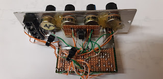
I managed to get everything on an 18 by 24 hole wide piece of stripboard. Six potmeters and eight output sockets on the panel, and an extra little print for the two bi-colour rate indicator LEDs which I made separate from the main print just like on the Dual LFO and as mentioned before a second little print to mix the two variable outputs together. The panel I made for it is 9 HP wide (4.5 centimeter). You might be able to make it even smaller if you use smaller potmeters in the panel. Even though I included an L-Bracket in the layout, I didn't use one. The stripboard is actually hot-glued in place in between the two columns of potmeters straight to the back of the panel making sure no copper strips make contact with the metal of the panel. I did this to keep the overall depth of the module as low as possible.
I did not include a Eurorack power connector on the print although there is room enough left to put one in. Instead I made a powercord with a Eurorack connector at the end so it always stays connected to the stripboard. This is handier because eurorack ribbon cables take up space too and this is a smaller footprint solution with only three thin wires.
This is mainly a Eurorack project but naturally this circuit will work just as well in a Kosmo sized synthesizer. I optimized the circuit to run on +/-12V but it was originally intended to be run on +/-15V. You will get higher amplitude waveforms when you run this on a dual 15V powersupply so if that's a problem for you, you can change the 1K8 resistors I used on the waveform outputs back to the 1K's you see in the schematic. The original schematic uses +/-15V.

SCHEMATIC:
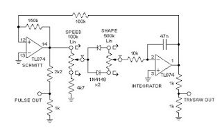
Below is the schematic I used for my layout. I put in bigger timing capacitors because I wanted one LFO running really slow and the other to about 20Hz. That is more useful for my modulation needs but you might want different values so I strongly advise you to do some testing with different capacitor values to get the LFO in the frequency range you desire.
The types of quad opamps and the one dual opamp used in this project are not critical. The schematic calls for TL074 and TL072 opamps but you can use anything with the same pinout. I used two LM324's and an NE5532 dual opamp. Btw, I did not include the transistor with the rate LED as seen on the schematic but I designed my own circuit for that so I could use bi-coloured LED's. It's just two opamp voltage followers (or buffers) feeding the LED's with the signal from the Pulse output. You can connect them to any output you wish but the pulse is the clearest for the LED's.
Here's the schematic drawing. Beware the opamp numbering does not follow the opamp order I used in the layout.
  

LAYOUTS:
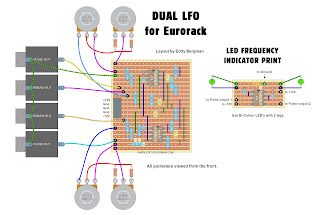
Below are the layouts I made for this project. As ever they are verified. I used them for my build. I changed the order of the opamps used from the order on the schematic. I setup one LFO using all the opamps on the left hand side and the other LFO using all the opamps on the righthand side of the IC's on the stripboard. That made it more compact plus easier to keep the overview. Luckily I did not need to make any changes or do any troubleshooting. I built it and tested it and everything worked first go.
You need four 100K and two 500K linear panel potmeters to this project. Measure and test them before you use them. That can save you some troubleshooting later. If you plan on mounting the stripboard to the panel with hot-glue like I did then try to solder the hook-up wires of the righthand side (the side that's glued to the front panel) as far to the middle as possible so you can still get to them once the stripboard is glued in place. This won't be possible with all wires but try. You could also solder them straight to the back/copper side.
Wiring diagram:


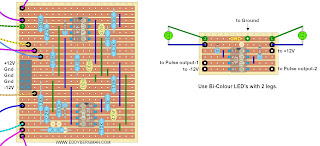
Stripboard only view:

Here are the cuts and wirebridges as seen from the component side! As always, I advise to mark the cuts on the component side first with a black waterproof marker pen and then put a pin through the marked holes and mark them again on the copper side. Then you can make the cuts accurately and you can see where the cuts are when you're soldering in the components.


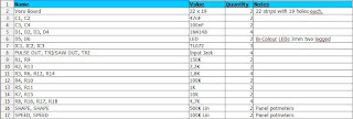
Bill of materials. 
The timing capacitors listed were chosen for my specific needs. I advise you to go by the schematic (47nF) or else test and determine the best values for your needs. You can use the Falstad simulation linked at the bottom of the article to test different values before building.
No bypass caps are included in this BOM because I didn't use any. They are on the schematic and you can put 100nF caps over the power connections on the IC's to ground if you want to. To do all IC's you'd need six 100nF ceramic caps (you don't have to do the LED driver IC).
This BOM does not include the components for the little mixer I added on further down the article. For that you will need 4 x 100K resistors, a 1K resistor and a 200K trimpot and a TL072 dual opamp.


PICTURES:
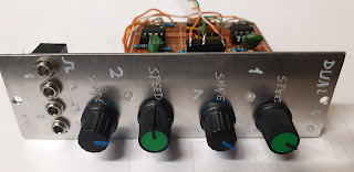
Here are some pictures of the build proces and the panel I made for it. I had some fill-in panels left from when I bought my 'Nifty Case' Eurorack case and I used one of them to make my front panel. It was already cut to the right height so ideal for this project ^___^  All I had to do was cut off a piece that was 4.5cm wide (9HP) and spray paint it. I labeled everything with an Edding 400 marker pen.

Wirebridges and cuts. I made some minor changes to the layout after I built this so there are a few discrepancies between this picture and the current layout.


Stripboard ready for testing side A:

Panel, not yet labelled:

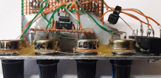
The finished module with the little 10 by 6 hole stripboard for the rate indicator LED's glued to the back of one of the potmeters. If you look closely at the sockets you can see I soldered all ground connections together with one copperwire going round them all. A wire goes from there to the ground connection on the stripboard.
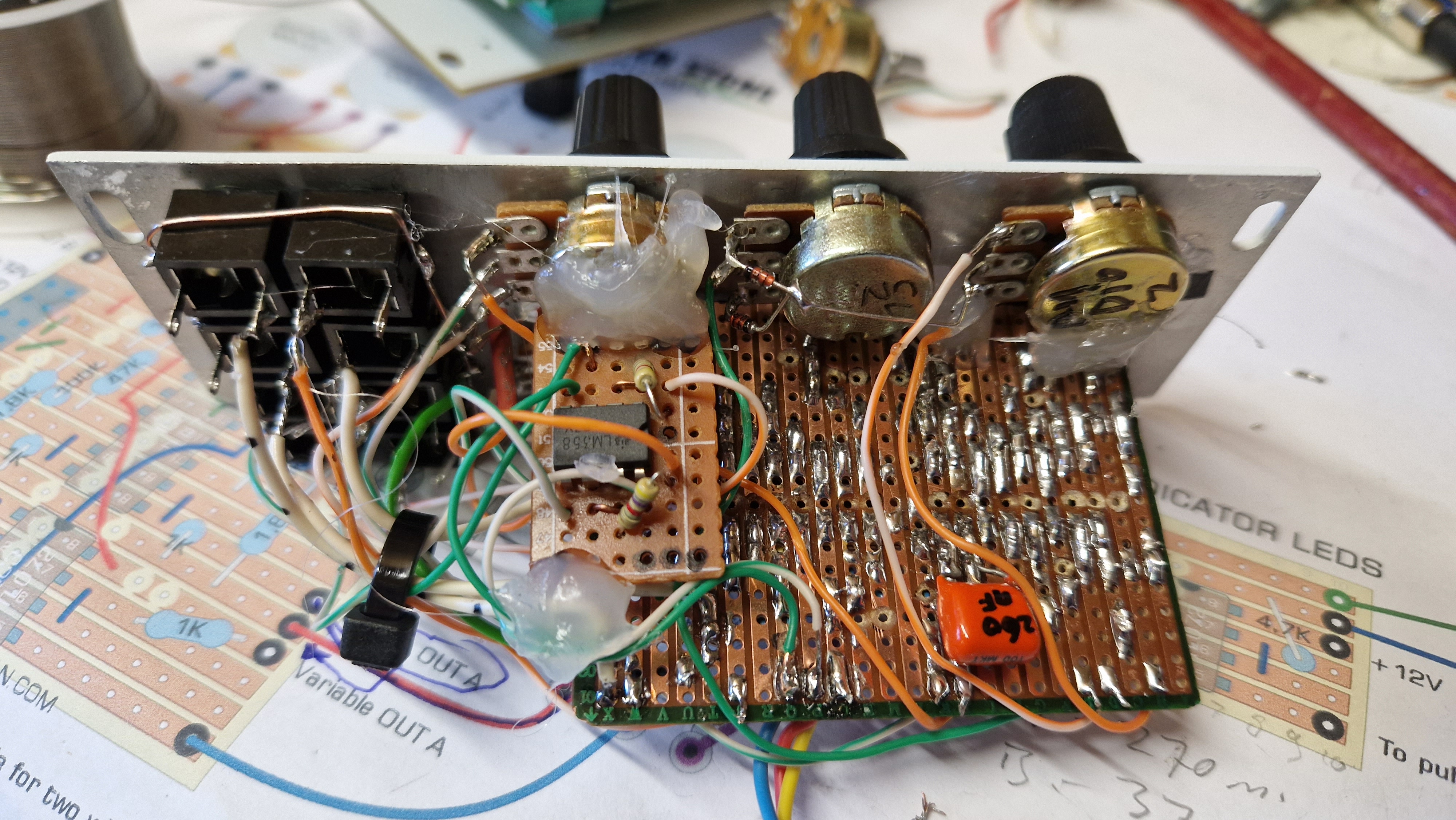

The finished product:


Here's a little demo video I made showing the LFO in action in a little Eurorack setup. You can hear how the 'Pico Voice' VCO changes in sound as I connect the LFO to it. But then I get distracted by the Pico DSP effects module and the 2hp Freez, LOL. Oh well. You can hear the difference it makes anyway :)


(As you may have noticed, I really suck at making demo videos, LOL)

WAVEFORMS:
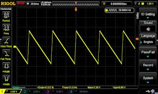
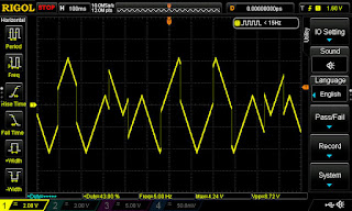
Here are some screenshots from the oscilloscope showing some of the waveforms. The one below shows the sharpest a sawtooth wave you can get. Pretty fast rise!


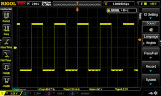
Cursor readings at LFO-B squarewave output:


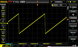
Here is a collection of variable output readings from Variable output B:


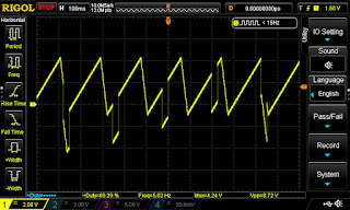
To give you an idea of what can be achieved by mixing the two variable outputs in a simple passive multiple, here are eight images I put together to give you an impression. This should sound awesome with very slow running LFO's which is why I soldered a few more caps in parallel over the timing cap of LFO-B.


You can imagine that some of these waveforms, when put through a quantizer, would generate awesome melody- or bass-lines that can be easily manipulated with the LFO parameters. I tried to capture a little of that in the demo video I posted below.

Here's some technical data from the LFO:
LFO A: freq. range: 270mHz to 24Hz. 
LFO B: freq. range.: 41mHz (one full cycle every 24 seconds using a 650nF cap) to 2Hz.
Duty cycle of the pulsewave output goes between 2% and 98%. I made a mistake and used a 100K potmeter for the Shape but it needs a 500K potmeter. I only had one 500K pot so I put it in LFO B and the screenschots above are from that LFO. You can use a 100K for shape but that will significantly lower the range of the duty cycle (20 to 80%) also the slope of the Saw-/Rampwaves will be slower rising. It will also speed up the overall frequency of the LFO.
Maximum current draw = 20mA for both the positive and negative side.
The maximum amplitude of the waveforms is about +/-5V except for the Variable waveform output. When that potmeter is set to the mid point the output amplitude drops to about +/-2.5V because the potmeter acts as a voltage divider so in the mid position the amplitude is half of what it is when it is fully clockwise or counter clockwise. (We effectively have two 50K resistors on either side of the wiper of the 100K potmeter.) These may seem like low voltages but keep in mind that an LFO is usually attenuated anyway because if the changes are too big it just doesn't sound good on a VCO or in most patches. If you really need higher voltages you can make the 1K8 resistors on the outputs even bigger.

Here's the link to the Falstad simulation of this circuit. This is the Dual version with one speed potmeter at 100K and the other at 500K as it is in my LFO. You can change these variables by right clicking on them and choosing 'Edit':

EXTRA FEATURE:
Okay as I write this it is four days since I posted this article and the cool looking results from the mixed variable outputs kept going through my mind. I really wanted to incorporate that into this design and now I found a way. I used an other small piece of stripboard on which I soldered a dual opamp and wired it up like the mixer in article 17 with 2 inputs. I knew there was no way to put an extra output socket on my panel so I sacrificed the squarewave output of LFO-B. That was the least useful of the outputs because I can get a squarewave anyway from the pulse output if I need one and I still have the squarewave of LFO-A. So I carefully soldered in the little mixer print which was just as big as the little LED driver and wired it all up and I re-labelled Square output B into 'Vari A+B'. I used a 200K trimmer to go over the inverting input of the second opamp and the output so I could adjust the gain and make it a little higher than the Variable outputs. I placed the little print above the sockets and used hot-glue to stick it in place. It is actually glued to the little LED driver board. This works perfectly! Now I have an output with two variable waveforms mixed together coming out of it.
Here is a picture showing how I added the mixer. I used two rigid copper wires to tap the signals from the sockets and lead them into the mixer. The non-inverting inputs of the opamps are connected to ground on the copper side:


Here's the layout of this little mixer. Mine is even smaller than this layout, but this will work fine. All resistors are 100K:

Here's the schematic for this little mixer:


DEMO VIDEO:
Finally I want to show you a little experiment I did using the new output. I put the Variable A+B signal through a quantizer (the 2hp Tune) and from there into the Pico Voice Wavetable Oscillator. The audio then went through the Pico DSP for some added reverb. You can really generate the weirdest melodies with this although this setup would benefit from the Voltage Processor because the negative phase of the signal does not produce any notes so it needs a positive offset voltage and the signal can do with some attenuation to get the notes closer together but I think you get the idea watching this short demo:


Okay, that's it for now. Article 50, wow I can hardly believe it. This journey started for me in October 2019 and I knew nothing about synthesizers then, but I was determined to get to grips with it and learn as much as possible. And what better way to learn then to build your own modular. So here we are more then 3 years and 50 projects later with a cool collection of builds helping hundreds of people to do the same. I'm really proud of what, not only I created but also of all the people who helped so much along the way with comments and directions. I'm not gonna name names but you know who you are, all of you. Thank you!! So many people told me they find the site a great help in their hobby and that's the biggest reward I could wish for. I am however going to wind down the DIY aspect of the hobby because having now built my own system and also haven gotten into Eurorack, I need to spend more time actually using it and figuring out how to use it all together. But I will remain available on Facebook and here to answer questions and help as much as I can to ensure you have a good experience using this website and get as much enjoyment out of it as I did.

PCB Version.
I recently made some Eurorack friendly PCB's for this LFO including the Variable output mixer I added on.
Here's the KiCad schematic I made for this LFO:


To get your PCB, goto the Menu and click on the top option called 'PCB Service' to find these circuitboards.

If you have any questions please put them in the comments below or post them on the special Facebook Group for this website where there are some awesome people willing to answer your questions.
Saturday, 15 January 2022

Synthesizer Build part-47: DUAL LFO for EURORACK.

A simple LFO with pulsewave (with variable pulse width) and a seamless transition between a Ramp wave, Triangle wave and Sawtooth wave using one potmeter. With LED rate indicators and Speed and Shape controls.

Well what more is there to say about this LFO. It's such a simple design that I could easily fit two of these on a small piece of stripboard and still have it small enough to fit a normal Eurorack case. The circuit is derived from the 'Utility LFO' by Ken Stone which is a larger version of this LFO. 
I now also have a project for the complete Utility LFO and it's even smaller than this one and a panel width which is only 1HP wider at 9HP.  Go to project 50 for that.  
This LFO is still useful on its own though because it is so small. It can easily be incorporated into other projects as an on-board LFO for instance.

The depth of this module is 55mm. I made the panel 4CM wide, that's 8hp, and I put the potmeters to one side leaving enough room to glue the print straight to the back of the panel at a 90° angle using hot glue. All the output sockets fitted nicely next to eachother at the bottom.
Naturally you can just as easy build this module in the Kosmo size and run it on 15V. If you do, you need to keep to the resistor values as they are in the schematic, not the layout because as I mention further down, I changed the 1K output resistors to 1K8 to get a nice +/-5V output signal. If you power this with 3 more volts you probably don't have to do that. Do some testing first to make sure though.

I tried my hand at using Falstad recently and tried to make a simulation of the complete Utility LFO circuit and it was surprisingly easy to do. 
So here is my very first ever Falstad simulation: --- CLICK HERE ---

Here's the schematic drawing of the dual LFO circuit:


The module consists of two of these circuits on a single piece of stripboard. I placed the LEDs on a separate piece of stripboard with a dual opamp, the good old TL072, and I used bi-coloured 3mm LEDs in red and blue. I drilled two 3mm holes to the left and in the middle of the first two- and last two potmeters for the LEDs and glued them in place with hot glue so the little print sits over the potmeters. See pictures below for illustration. Btw, you can use any dual opamp chip for this circuit as long as the pinout is the same; like the TL082, NE5532, LM358 etc.

LAYOUT:
Here is the layout I made for this Dual LFO. As always, the layout is verified. I used it for my build. I placed the Eurorack powerconnector on the left side for better access. In my build it's on the other side and very near the panel. Not a good place for a power connector but you only find these things out when you start building it. See, I make the mistakes so you don't have to LOL! (I hot-glued the print to the back of the panel with the righthand side closest to the panel.)


Stripboard only:


After doing the first tests I found the output voltages a bit on the low side. They were just +/-3,24V so I decided to experiment with the 1K resistors between the outputs and ground. I tried several values and I ended up using 1K8 resistors. That brought the output voltages to a nice +/-4,8V. Almost 5V so that's perfect for eurorack. If you want that voltage to be even higher in your LFO then experiment further with making the resistor(s) between the output socket and ground even higher in value.
I wanted to make one of the LFO's a bit slower than the other to give me a wider overall range so I used a larger capacitor for LFO number one. I used a 147nF and that made it perfect for my needs, between 0,2Hz and 10Hz. In the layout both timing caps are 47nF though.
 
TECHNICAL DATA:
Here are some measurement results for this Dual LFO:
Duty cycle of squarewave is 5% to 95% this varies a bit with the frequency but not more then 2%.
Lowest frequency: LFO-1 = 0,219Hz  LFO-2 = 0,653Hz (changed timing cap of LFO-1 from 47nF to 147nF)
Highest frequency: LFO-1 = 9,82Hz   LFO-2 = 34,2Hz
Output voltage is +4,8V or 9,6Vpeak-to-peak. That's after changing the 1K resistors in the schematic for 1,8K ones. Otherwise the voltage was just 3,2V and 6,4Vpp.
Current draw: positive: average 12mA max.: 18mA
                       negative: average -13mA max.: -18mA

Here's the Bill of Materials:


Here are some screenshots from the oscilloscope with some measuring data underneath the images. Some images may still show the lower output voltage but that's been fixed:


The following are screenshots from the oscilloscope showing two signals, one from each LFO, being combined in a simple passive multiple. A squarewave and a triangle wave each at different frequencies. The results are pretty cool looking:


In the top picture you see more of the waveform in the positive voltage region and very little below zero Volts. You can set that with the shape potmeters to your own liking or best sounding result. As you can see this makes the Dual LFO module much more versatile as a modulation source. Plenty to experiment with.


PICTURES:
Below are some pictures of the print. I took these before I changed the 1K resistors to 1K8 ones. In the top picture and the 3rd one you can see how I mounted the little print with the bi-colour LEDs. The print rests above the middle two potmeters and the LED's are bent backwards over the sides of the stripboard and go straight into the holes in the panel and are secured with hot-glue. The little print itself is not mounted in any way. It just relies on the LEDs to keep it in place.


This time, instead of spray-painting the panel I decided to keep it blank aluminium and I used an engraving tool to put the text on. That didn't work too well and it didn't look good at all so I printed some labels I made in Photoshop, laminated them with Scotch Tape and put some double sided sticky tape on the back and I put those on the panel. That looks much better. 

TRIGGER OUTPUT
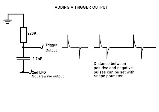
A few days after completing this build I added a trigger output to this module. I connected it to the squarewave output of the second LFO (the faster one). I thought it might come in handy to have a trigger source. You can see in the picture below how I did that. It gives of both positive and negative trigger pulses of 5V and a length of about 4mSec.  If you're thinking of putting in a diode to only get positive pulses forget it. That won't work. It'll kill off the pulses completely. If you turn the Shape potmeter the positive and negative pulses will move further away or closer to eachother. Just like the rising and falling edges of the squarewave with different pulsewidths.


(The above drawing actually translates to a high pass filter with a cut-off frequency of 268Hz. So it filters out the actual square- or pulsewave and only lets through the initial harmonics of that wave, creating this spike pulse trigger response, but you can forget about this theory. This is not important.)

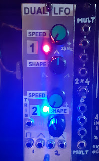
Here's a look at the final panel with trigger output. I just made some labels with text to put on the panel. Looks better than the engravings.


One other thing worth noting is that because we have two LFO's on one board, they will very slightly influence eachother. What I mean is, if you have one LFO running at almost twice the speed of the other, the faster one will adopt some multiple of the rythm of the slower one if you set the speed to some value close to that. That's a form of resonance and I won't get into the technicalities of that but it's quite easy to set an LFO at twice or 4 times the speed of the other because they share the same circuitboard. It's the same idea as when you have a group of people walking together and they all start to walk at the same pace. That's also a form of resonance. Don't think this will be an obvious thing to observe. The occurrence is very subtile.

Okay, that's number 47 done! A very useful little module and I saved a few bob by building it myself instead of buying a dual LFO module. Okay it doesn't have any fancy extra's like synchronization but that's okay by me. I think I'll mostly be using this as a clock source and some random modulation. That's why I made both LFO's run at different frequency ranges.

If you have any questions or remarks about this or any other project on my site please comment below or post in the FACEBOOK GROUP for this website.

If you find these projects helpful and would like to support the website and its upkeep then you can buy me a Coffee. There's a button for that underneath the menu if you're on a PC or Mac. Or you can use this PayPal.Me link to donate directly. All donations go towards the website and projects. Thank you!

Sunday, 10 May 2020

Synthesizer Build part-32: ELECTRIC DRUID VCLFO-10 with extras.

A truly awesome LFO with 16 waveforms and 8 different controls. I added 2 extra outputs for 10Vpp and a frequency indicator LED.

This Low Frequency Oscillator was one I had on my wish list for a long time. Last month I decided to buy the chip, it was only 5 Pounds anyway, and it arrived precisely a week later from Tom Whiltshire of Electric Druid in Portugal.
I downloaded the Datasheet PDF with all the schematics etc on it but I found parts of the schematic a bit confusing. The Frequency and the Level controls have their own opamps and they both have two potmeters connected which looked a bit weird to me. So I asked on the Synth DIY Facebook Group what the deal was with those two potmeters. It turns out both the Level and the Frequency controls can be connected to an external control voltage so one potmeter is connected to an input jack and serves as the input level control or attenuator and the other potmeter is for manual setting of the Frequency and the same for Level. So after I had that straight I set about making a stripboard layout. Now, I noticed there was no rate indication LED in the schematic. I always find it handy to have a frequency indicator LED on the panel, so I designed a second board and included a rate indicator LED on it, together with two extra outputs that have a DC offset of +5V so the outputs are 0V to +10V. That is the level I use most on my synthesizer so I needed to have that included. This does mean that the Noise level through these outputs has a +5V DC offset so use the +/-5V output for noise.
I made a second stripboard layout and made a mounting hole in it, on the upper right corner, so the second board can be stacked on top of the main circuit board, using a 3 cm M-3 bolt  and a bit of plastic tubing as a spacer to keep the two boards from touching eachother. The layouts worked like a charm and everything worked fine when I tested it.
 
If you find that you wired up the potmeters the wrong way around, you can easily correct that by connecting pin 2 of the VCLFO chip to ground. That reverses the working of the potmeters. Make sure the two level potmeters are wired like on the diagram though. They are not influenced by pin 2 of the chip.
The main stripboard has its own plus and minus 5V power supply included, so everything can be powered from a single dual 12 Volt power supply. I used the big 7805 and 7905 in TO-220 package because that's the only ones I had available but you can use the smaller L versions. This circuit hardly draws any current at all so they won't run warm and don't need heatsinks. I did not include any de-coupling capacitors or electrolytic caps on the power rails (except for the -5V because that was indicated in the schematic). You can put those in though, if you think you need it. Use two 100nF ceramic caps, one from +12V to ground and one from ground to -12V.

SYNCHRONIZATION POTMETER:
There is an extra 100K trimmer in the layout with which you can set the Synchronization mode between Sync Off, sync-ing the LFO, the Sample and Hold or both. Instead of a trimmer, as seen on the layout,  you can also make this a feature on the front panel and connect a potmeter to the same points as where the trimmer now sits, and of course you then leave out the trimmer. That way you can change the sync setting on the panel itself. This is what I later did. Beware these extra's are not listed in the Bill of Materials. I used a 100K potmeter but you can use any value potmeter or trimmer for this function because it is just a voltage divider connected between +5V and ground. (Use a value of 10K or higher.)
Looking at the panel-potmeter front-on with pins pointing downwards, connect the left pin to ground, the middle pin (wiper) to pin 8 of the chip and the right pin to +5 Volt.
It took me 5 and a half hours to solder the stripboard components in place and to wire it all up. The whole proces of designing the layout, designing and making a panel etc. took a whole weekend so it was a nice project to do because at the time I, and everyone else, was stuck at home in Covid Lockdown anyway.

Here is the (verified) layout. Wiring diagram:


The +5V and -5V points on the left side of the stripboard are simply indicators, so you know that voltage is available at that point. You could say they are test points you can check if you are troubleshooting this board (which of course I hope won't be necessary. ;) But nothing needs to be connected to those points. Sorry if that's a bit confusing.
This circuit will run fine on +/-15V too. The voltage only feeds the IC's and the regulators and they can all take it without problem or without any changes needed.

Here's the layout for the main stripboard. Beware that some stripboards are sold with 56 instead of 55 holes horizontally. The layout is 55 holes wide!!
In this layout the synchronization mode is set with a 100K trimmer at the top of the stripboard. As I mentioned before I myself changed that for a panel mounted potmeter later. The sync mode depends on the voltage on pin 8 and the trimmer or potmeter sets that voltage.
There is no capacitor on the input of the 7905 voltage regulator, it doesn't need one to work but if you want you can put a 1µF electrolytic cap over the input to ground. Easiest way to do that is to connect it to holes B-11 and C-11 with the negative pole in position C-11 (-12V)


The Zero Adjust 100K trimpot is used to set the symmetry of the output signal. You must use an oscilloscope to adjust this. Set it so the LFO output signal's positive amplitude is the same as the negative amplitude.
Make sure you get the cuts right in the stripboard. Especially those in the power rails at the top otherwise you'll have a direct short circuit between ground and -12V. Always measure continuïty over the power connections to rule out short circuits before you connect it to power for testing.

Here's the Bill of Materials for the main stripboard. Note: component numbering does NOT follow the numbering in the datasheet schematic. 


OFFSET AND LED INDICATOR BOARD:
Here's a close-up of the second board with the extra outputs and rate indicator LED. You can use this board for other projects too, if you need to add a DC offset voltage to a certain output. I chose 150K resistors for around the opamps (R3,4,5 and 6) because I have a lot of them but you can use any value from 47K to 500K instead of the 150K's as long as you use the same value for all four resistors:


The DC Offset trimpot must be set to a +5VDC Offset to get a 0V to 10Vpp output signal. Use an oscilloscope connected to the output socket to set this. I don't have a schematic drawing for this part but it's a really straightforward opamp offset circuit with the offset trimpot connected to the non-inverting (positive) input of the opamp. The signal goes in at the inverting input and then it goes through a second opamp stage to invert it back to normal again. Then the second output (at the bottom) is simply fed the signal of the first output via an opamp buffer. The second opamp of the chip on the right is not used and properly connected to ground to 'park' it, so to speak.

Here's the Bill of Materials for the extra board:


You don't have to use this extra board for 0 to 10 Volts outputs of course. If you find you need more Bi-Polar outputs of +/-5V then set the trimmer to 0V offset and it's done. 

WAVEFORMS:
This VCLFO produces 16 waveforms in 2 sets of 8. I have made a little compilation image of oscilloscope images I took of the waveforms and some sample and hold results. The blue line is the original +/- 5V output and the purple line is the one I put in myself with 0 to 10Vpp. You can see that the noise has a +5V DC Offset on the purple line. When you start testing this circuit after completing the build, it's possible you don't see a waveform but just a flat line. That means your offset voltage is too high or too low, so all you need to do then is set the offset voltage with the trimmer on the main stripboard. Then check the 10V outputs and set that offset with the trimmer on the small print. I advise to use multiturn trimmers for those, but you don't have to. Make sure your oscilloscope is set to DC mode for measuring these waveforms.


Each of the waveforms produced can be sent through a sample and hold unit which is built into the chip and as the chip can also produce noise you can also get random tones produced by this LFO if you connect it to the CV-2 input of one of your VCO's. The sample rate of the S&H can be set with a 10K panel potmeter and if you turn it to zero the S&H switches off automatically.
The VCLFO has a synchronization input and it can be frequency modulated by means of a Frequency CV input with attenuation potmeter. There's even a separate input for the Level control which is a volume control changing the amplitude of the waves.
There's also a control on the panel for 'Distortion' which bends the bottom or top part of the wave with the middle setting being the clean, undistorted wave.
The LFO has 4 frequency ranges and they are:
8 seconds per wave to 12,5 Hz
4,6 sec/wave to 25 Hz
2,6 sec/wave to 50 Hz
1,2 sec/wave to 100 Hz
You set the frequency range with the LFO Range potmeter and then you can set the Frequency within that range with the Frequency potmeter. There's a smoothing switch included in the circuit which rounds off the corners of the waves and makes them smoother (obviously, LOL). This is to prevent the sharp edges of some waveforms from causing clicking sounds when you're using the LFO as a Tremolo.
The possibilities are endless with this LFO and with the chip only costing 5 UK Pounds, like I mentioned, you should really get this one.

Here are some pictures of the finished panel and of the stripboard and wiring. I admit the panel is a mess but it works for me:


In the picture below you can see I made a change by adding an extra potmeter (the one with the yellow knob) with which you can set the Synchronization mode between synchronizing the LFO, the Sample and Hold or both.


And here's a little video I shot using the LFO in a reasonably complicated patch. I've got 3 VCO's feeding squarewaves into 3 filters and a triangle wave into the wave folder. Each filter receives an LFO signal from a different LFO. The Electric Druid VCLFO-10 is feeding a quad pulse into the Steiner Parker filter. All LFO's are synced from the main LFO which is the Music From Outer Space LFO. You can also see the Mixer/Passive Attenuator in action with the bright blue clipping LED coming on occasionally and the Digisound 80.6 LPF sounding really good!


If you're interested in recreating this patch then here is the basic set-up I made. The eventual sound is, of course, dependant on the settings of all the potmeters and little changes can make a big difference but this at least is the foundation of this patch:


ORDER THE CHIP:
Here is a link to the product page of the Electric Druid VCLFO-10 from where you can order the chip:  https://electricdruid.net/product/vclfo-10/

If you have any questions about the chip or simply want to say thanks to Tom Wiltshire, drop him a line on his website. He's a really nice guy and he'll appreciate your feedback.

Okay, that's it for now. I have now finished the second stage of my synthesizer and so I have no more room to put new modules unless I build a third case. That will no doubt happen but not right away, what with summer coming it's going to be too hot in the attic to spend all day in there wood-working or soldering. I also built up a Eurorack system in early 2022 which took a big chunk out of my budget, which wasn't/isn't too big anyway, but that's all in the game right?

As always, if you have any questions please post them on the EB Projects Discussion and Help Facebook group, or in the comments below or contact me directly via Facebook.

Sunday, 3 May 2020

Synthesizer Build part-30: LFO with SYNC and FM INPUT (Yusynth).

A very useful LFO with synchronization and Frequency Modulation input, using the ICM7555 IC. This is an other Yusynth design.

I seem to be building a lot of Yusynth designed circuits lately but that's because I know they work so well. This LFO is no exception although the waveforms don't always come out perfect. There are some spikes and weird anomalies to content with sometimes, so please consider this a bit of an experimental LFO. It really prefers to run on a dual 15V powersupply although it'll work on dual 12V too. This is a medium difficulty project. I wouldn't advise it for beginners. Just take a look at the layout and you'll know what I mean.
This LFO circuit uses the well known ICM7555 chip as main oscillator and two TL074's (or TL084's or any other equivalent) to produce the different waveforms. The 7555 is the CMOS version of the NE555, Do NOT use an NE555 in this circuit! 
The LFO has 4 outputs, one for Sine-, Triangle-, Squarewave and Ramp wave. It has a switch for two frequency ranges. The normal setting (x1.0) goes from about one cycle per 14 seconds to about 100Hz. Then there's a x0.1 setting that divides this roughly by ten so you get (in my case) one cycle per 60 seconds to 18Hz but this can be set with a trimmer on the print so you can set it to your own liking. 
Because the layout is pretty chaotic looking, you need to go about this build very methodically. Mark out all the cuts you need to make first. I've made a special layout with just the cuts on it, to make it easier for you to do this accurately.
I must say I absolutely love this LFO. It has quickly become my goto LFO for modulation duties. It's particularly hand for modulating the LowPass Gate because the speed can be modulated with an ADSR for instance so a sound can start off sounding continuous with the LFO driven into audio range by the Envelope Generator and then lowering in frequency, fading out into a pulsating beat created by the Lowpass Gate. It's awesome :)

STRIPBOARD LAYOUTS:
Here's the stripboard layout I made for this LFO. I built mine using this layout so it's verified. All wire bridges connecting to ground are coloured green. Btw, you can use other values for the 50K panel potmeter. It's just a voltage divider level pot. You can use 10K or 100K or 1M, whatever you have available.
Naturally, instead of having a switch to go between Saw and Inverted Saw (Rampwave) you can install two output sockets and have both available at once. That's up to you.
Instead of the 50K resistor at the top right, you can use a 47K one.
Wiring diagram:


Stripboard only. Beware that some stripboards are sold with 56 instead of 55 holes horizontally. The layout is 55 holes wide:


Here's the overview of where the cuts need to be made. I usually mark them with a black Sharpie on the component side, because that way they are easier to identify from the layout, and then I stick a pin through the marked holes and mark them again on the copper side. (That's why I'm showing both sides here). Then I cut the copper side with a 6mm or 7mm drill bit (or a Dremel-tool) in the marked places.


Bill of Materials:


Here's the schematic I used for the layout:


You can see in the schematic that there's a fifth output, underneath the saw output. This is an inverted version of the sawtooth wave and I installed an extra switch to give you the choise between Saw or Ramp. (The un-inverted version is actually a Ramp (rising voltage) and not a Saw, but whatever.)
All waveforms are bi-polar, they have the zero volt line as their mid point so they have a negative and positive phase.
Here is the result of some measurements I took from the LFO:

In the x1.0 setting:
Frequency Range = 1 cycle per 14 seconds to 100Hz
Squarewave amplitude = +5 to -5 V.  Duty Cycle = 26% to 86%
Sinewave amplitude = +5.3 to -5.3 V
Triangle wave = +7 to -7 V
Sawtooth wave = +7 to -8 V

In the x0.1 setting:
Frequency Range = 1 cycle per 60 seconds to 18,7Hz
Amplitudes are the same.
Squarewave duty cycle = 18% to 98%

The synchronization pulse threshold = +2,9V.

As you can see, a fantastically broad range of options and synchronization works very well. When you put a high amplitude sawtooth wave on the CV input the resulting frequency sweep can reach well in to the 400Hz (in x1.0 setting). The LED indicates the frequency rate and is connected to the squarewave output so it will react to changes in duty cycle by being on longer or shorter.

Calibrating the circuit:
You can set the Frequency range by turning the Rate panel potmeter all the way counter clockwise and then use trimmer T1 to set the lowest rate.
Trimmer T2a and T2b are used to set the sawtooth wave in such a way that the positive phase has the same amplitude as the negative phase. In other words you set it so the zero volt line runs right through the middle of the wave. There are two of them because one is used in the x1.0 setting and the other in the x0.1 setting, so only one of those trimmers is active at any one time. Therefore you need to set this twice.
Trimmer T3 is used to set the Sine symmetry. Turn it so that the top of the wave has the same curve as the bottom of the sinewave. This potmeter also influences the duty cycle of the square wave, so you need to set the duty cycle panel potmeter in the middle position and trim the Sinewave so it looks good and then look at the Squarewave and make sure the panel potmeter for duty cycle can be used over its full throw. To make things even more complicated, this trimmer also has an effect on the shape of the Triangle wave so it's a bit fiddly but you need to go between all of these three parameters and find the right setting. You'll get the hang of this soon enough though. It sounds more difficult than it really is. You just have to find the setting that looks the best for all three waveforms. A multi channel oscilloscope will be of great use here.
If you can not get the waveforms right you need to change the 1µF and 10µF capacitors for some other ones with the same value. Yusynth says to use Tantalum caps here but I tried those and it only made things worse. But you may have a different experience. You need to be able to experiment, an other reason why this is not a beginners project.
One other thing which I became aware of through reader feedback; if your output levels are very low and transistor Q1 gets hot then you might be using fake chips. I've had feedback where this problem turned up and changing the chips for ones from a reputable source fixed the problem. So once again, make sure your chips aren't fakes from China.

The x1.0 and x0.1 frequency range settings.
Calibrate the LFO in the frequency setting that you think you will be using most. If you get the waveforms right in the x1.0 setting then the sinewave may not look ok in the x0.1 setting.  That's a little quirck of this LFO and difficult to get right but I usually only use an LFO in the 10 second to 10Hz range, so if all is well in the x1.0 setting, then that's good enough for me. The duty cycle range of the squarewave varies too, according to how the frequency range switch is set. It's really only the sinewave that I personally can not get right in the lower frequency setting. It rises normally and then drops off so it's more like a sine version of the ramp wave. But that's the only thing I can't get right. I found that adding a 0,1µF electrolithic capacitor in parallel over the 1µF cap helps in getting it all looking good. This however will vary from build to build with component tolerances etc.

12V vs 15V:
This LFO will work on a dual 12V powersupply but the frequency will go down by a large amount but you can turn that up again with the trimmer T1 on the stripboard. The amplitudes of the waveforms will go down to between 2 and 5 Volt so that is significantly lower. The LFO is not really meant to work on +/-12V but it will work. However, if you need to address this problem I advise to make an extra board with a TL074 quad opamp chip and set these opamps to a gain of 2 and have all the waveforms go through it. That will double their amplitudes. You can also give them a DC offset voltage to keep them all at a positive voltage if that's what you need. However, if you're a beginner and don't know how to do the above mentioned then you can use the quad offsetboard project for this. Or just build the LFO and run it on 12V. LFO outputs are usually attenuated anyway so the lower amplitude signals will still be very useable. This will be a module you will use a lot! I guarantee it.

Here are some screenshots of the waveforms. You will need to try and trim the negative spike in the top of the Triangle wave away while keeping the sinewave looking good. I don't think it's possible to get rid of it completely but you won't hear it in normal use. I've built a few of these now and the waveforms don't always come out looking this good. Beware this LFO is not perfect.
As you can see from the screenshots this is a bi-polar LFO. Meaning the output voltages go both positive and negative.


The result of introducing the synchronization pulse. The waveform resets at the rising edge of the sync pulse and will remain high until the pulse falls away. Short trigger pulses will work best here:


Here's what happens when you put an inverted ramp wave (from high to low) on the FM Modulation input (CV IN). You get a frequency sweep that can be quite high in frequency, but you can set the level, and with it the maximum frequency, with the FM Level potmeter. You can see that the amplitude drops a bit in the higher frequencies for some of the waveforms:


Some pictures of the finished module:


I am thinking of adding a second print, like I mentioned earlier, with just a single TL074 on it to use the 4 opamps to give the 4 waveforms a +5V DC offset so they go from 0 to 10V and stay in the positive voltage range. Edit: There's now a Dual Voltage Processor project on this website that can be used for this purpose too.

To conclude this article I made a little test video showing off the 'Synchronization' feature of this LFO, which was the main reason I wanted to include it in my modular synth. As you can see it works very well:


Here's a Falstad simulation of this circuit which I drew myself. It's not working quite like it should but it gives a good indication of how the circuit works: -- CLICK HERE --


Okay that's article number 30 done! Quite a milestone for me I must say, to write 30 articles in so short a time. As per usual, please put any remarks or questions in the comments below, or post them in the Facebook Group for this website.