Showing posts with label multiple. Show all posts

Friday, 4 February 2022

Synthesizer Build part-48: PASSIVE MULTIPLES and SWITCHED PASSIVE MULTIPLES.

The simplest modules you can build but they will be the ones you use most often because each modular synth needs at least a few of these.

This will probably be the shortes article on this website and the simplest of projects but I just thought I'd mention these multiples here because recently I built a few for my Eurorack case and some newcomers to this hobby might not be aware of them. They are so useful to have in your setup.

Multiples are passive devices because they do not require any power source. They just split up signals so you can have 'multiple' sources of the same signal (hence the name). You put the output of an audio or CV source into one of the sockets and then you can tap that signal from the other sockets to turn one output into multiple outputs.
There are two versions of these that you can build.
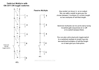
The straight forward passive multiple that consists of just a number of 3,5mm female sockets connected together. Usually it's between 8 to 10 of these underneath eachother. You can add a switch in the middle so you can split it into two rows of half the number of sockets. That way you can use if for more than one signal source.
Then there's the switched multiple. That's the same idea only now each socket has a 2-way switch next to it, with a middle off position. Each switch has their left pins connected together underneath eachother and the same for the right pins and the middle pin of each switch goes to a female jack socket. (see schematic image below)
This will allow you to put one of two signals on each of the outputs or switch that output off. This can be very handy in live settings where you want to switch between two sequencers for instance. So you need toggle switches with a middle off setting for these. At least, that's the best way of doing it. ON-OFF-ON switches. You can use ON-ON switches but then you can't switch anything off.
There are also buffered multiples like the one in project number 25 on this website but they require opamps so they are not passive in any way.

Here's a schematic overview of the multiples. The length of these is dependent on the space you have available on your panel. For Eurorack it's usually 10 in a vertical line for a passive mult or 8 if there's a switch in the middle. And for a switched mult it's usually also 10. For Eurorack that is. For a Kosmo sized panel there's room for much more sockets.


Here is a picture of the mults I made and built into my Eurorack case. This was rather hastily done on a sunday afternoon so it looks a bit rubbish (so what else is new) but that doesn't matter to me as long as it works. My switched mult (on top) uses dual pole switches because that's all I had so there's some redundancy built in because single pole switches are really all you need.


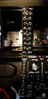
The bottom one has a switch in the middle so I can use it as one 8 socket multiple or two 4 socket multiples.

If you want to build Buffered Multiples with opamp buffers then you can go to this article here.
Buffered Multiples are often used to connect more then one VCO to a 1V/Octave signal, because with those signals it is important that the voltage on the input is reproduced accurately on the outputs, in other words it's not dragged down however many VCO's you connect to the multiple. Passive Mults with many things connected to them can draw the voltage down a bit wich would de-tune a VCO.

Okay that's all. Just a simple little item but one you will have to build at least once. The good thing about them is they need no circuitboards and you can use off-cuts of panel material to build a few of them.
Okay, until the next one!

Monday, 30 March 2020

Synthesizer Build part-25: DUAL BUFFERED MULTIPLE with LEDs.

A very practical module that replicates any voltage on the input and splits it 4 ways. Now also in Eurorack size. This is also known as a CV/Gate Expander but it's the same thing. After seeing Sam Battle's version with the bi-coloured LED's I've added a second version of my own with the bi-coloured LEDs because I think it will be in demand.  The version with LED's is half way down this article.

I have finished the case for the second stage of my DIY synthesizer so now I can continue building modules and writing about them here. So the first thing I wanted in the new case was a Buffered Multiple. I have built a number of filters that need a 1V/Octave signal but I only had one output to provide it so I designed this little circuit. You can connect anything you want to the inputs: Audio signals, LFO signals, 1V/Oct. CV, Gate signals, you name it. Any voltage presented at the input is replicated at each of the four outputs and if you need more you can connect one of the outputs of the first stage to input 2 and so get a total of 7 outputs for one input. 
I've added a Eurorack version with LED and, as a bonus, at the very bottom of this article there is a layout for a 3 x 4 Triple Buffered Multiple also in Eurorack format.

This module will work on both +/-15V and +/-12V.  Running it on 15V just means it can handle a bit higher voltages but as the average synth only uses control voltages with a maximum of +/-10V it really won't matter.
This the one module that is always in use in my synth because you always need a multitude of 1V/Oct. signals and Gate signals. It's been in constant use for 5 years now and never had a problem with it. 

Here is the schematic drawing showing one stage. As you can see it's just 4 non-inverting buffers with all the inputs connected together. The module is just two of these on one piece of stripboard. I've put 100 Ohm resistors on the outputs for some extra protection. Because there's (practically) no current flowing these resistors won't influence the output voltage. I've tried 1K resistors but they influence the voltage and bring the notes down by a few Cents. I did a lot of testing on this and 100 Ω is really the maximum. Of course you can use 1K and retune your VCO's but I want to keep it as clean as possible. If you don't feel comfortable with resistors on the outputs you can leave them out all together. In my own version I left them out too and replaced them with wirebridges. The IC's have built-in short-circuit protection anyway.

I've had some kind feedback in the comments of the Buffered Multiple not working right with Gate signals in combination with the Behringer TD-3. The Gate pulse would stay high. The solution was very simple, just put a 1MOhm resistor between the input and the Ground.  This is something I forgot but you must never leave an opamp input floating so there must be a resistor between the input and ground. I've adapted the schematic and put in the 1M resistor on the input. All the layouts are updated too.


To be quite clear because a lot of people miss read this: 
THE RESISTORS IN THE OUTPUTS ARE 100 Ω NOT 100K!!! If you put in 100K resistors you won't get much signal out at all. If in doubt put in wirebridges instead!!

Here's the verified stripboard layout. Just two IC's and some wire bridges and resistors. I recently added de-coupling capacitors for the chips because it was kindly remarked upon in the comments below that they were missing and it is good practise to include them.
Please don't forget to put a 1M resistor between between the input and ground (on both sides). The circuit needs these because opamp inputs should never be left floating. 


(Last revised 25-Feb.-2022: updated the layout and added 1M resistors to inputs.)

Stripboard only. The 100 Ω resistors can be replaced with wirebridges. In fact I would use wirebridges instead of resistors to begin with. I chose 100 Ω because that's the highest value that still doesn't cause a drop in voltage but you can easily do without them and use wirebridges instead. The resistors are there to offer some protection to the chip should you connect a live signal to one of the outputs by mistake, but most chips have internal protection from that anyway:


Bill of Materials:


BI-COLOURED LED VERSION:

Here's the layout for the version with the bi-coloured LEDs:
Wiring Diagram:

(Last revised: 11-feb-2022: added 1M resistor to inputs.)

Stripboard only. 


BOM for the LED version:


Make sure you choose the bi-coloured LED's with two legs and not the ones with 3 legs. They won't work in this set-up. They must be two-legged. You may need to alter the value of the 18K resistors according to the brightness of the LED's you're using but I find 18K to be a nice middle value. Not too bright not too dim either. I've altered my own Buffered Multiple to include the LED function and These 18K resistors work just fine with the Red/Blue LEDs I'm using. But you can use 5K6 if 18K is too dim in your case.
If you take a look at the demo video in the article about the "Really Good AS3340 VCO" you can see this Dual Buffered Multiple at work to the left of the VCO I'm demonstrating.
Below note E1 the Red light, which is positive voltage, doesn't light up but above E1 you can see it light up. The higher the note, the brighter the LED gets and it can handle voltages as high as 15V without problems. Above the lowest 2 octaves the LED shines about as bright as it will ever get. For the blue part of the light the threshold for the LED is higher, about 3,5 Volt. So it will need a tiny bit higher initial voltage to turn on, but that's not really a problem. But for accuracy it's better to use Red/Green LED's because of the lower threshold voltage of the green LED vs the blue one.
I've added 6 times gain to the LED opamp stage so that the LED will start shining at the lowest of voltages. The 510K resistor determins the Gain. The formula for calculating the gain is 1+(510K/100K)=6.1
Of course you could also use two normal LEDs; one for the positive cycle and one for the negative cycle. It's up to you.
The extra gain of the LED output stage works very well in practise. The LED has quite a good range in brightness and thus gives a good indication of the strength of the voltage present on the outputs.

Here's the schematic for the LED version. I've connected it to output 4 of each of the two sides but you can choose any output that's convenient. Because the LED is buffered it takes no voltage away from the output. This schematic drawing shows only one side because the second side is identical to this one.


This module is very useful to have in your setup because sooner or later you're going to need at least one of these, just like you need at least one mixer/passive attenuator.

Here are a few pictures of the finished product. I made a little L-Bracket (also visible on the layout) so I could mount the board at 90° to the panel.


This is the version with the LED's installed. The right LED is displaying the voltage of the Gate signal which is +5V. The left LED is displaying the 1V/Oct signal which is a bit lower and thus the LED shines a bit dimmer.


The print up close. As you can see mine has more wire bridges because I forgot that some connections can be made directly under the IC. So I did it the hard way. The first picture below is the original module without LEDs. The second one is after I converted it and added the LEDs.


Because I added the LEDs later I had to use some jumpwires on the stripboard to connect it all together.


EURORACK VERSION.
Single buffered multiple with one input and five outputs.
This is one I recently built for my eurorack case. It has 5 outputs because I added a dual opamp for the LED and that uses only one side so I had an opamp left over which I added to the outputs. I used 68 Ω resistors from the outputs to the sockets to give the opamps a little bit of protection should a signal carrying cable be plugged into an output by mistake (opamps don't like that). I didn't use IC sockets for this build because I've run out of those. I soldered the IC's straight in but that works fine and it also means bad IC-socket contacts won't be an issue so it makes it more reliable.

This layout is verified.


Here's the schematic. It's more or less a copy of the above schematic and I've put in the Bi-Coloured LED section with the 2nd opamp of the TL072. I lowered the value of the output resistors a bit from 100 Ohm to 68 Ω to be absolutely sure there's no voltage drop but you can use wirebridges instead of resistors too. The output resistors serve as a short circuit protection but opamps have that protection built-in nowadays. If you want de-coupling caps then put some 100nF ceramic caps over the power pins of the chips to ground as seen on the layout.


Here's the Bill of Materials for this version. The list has 100 Ω resistors instead of the 68 Ω in the schematic. Either of the two will work fine, even wirebridges work fine:


Here are some pictures of the finished eurorack module. It's 6hp wide (3cm) and 5cm deep. I used hot-glue to connect the stripboard straight to the back of the panel and next to the output sockets to which the stripboard is also glued for some extra support. Works very well and it's very sturdy. I soldered the power lead straight to the stripboard and also secured it with some hot-glue. 


As you can see in the last picture there's one ground wire going through all the ground lugs of the sockets and the cathode leg of the LED. From there a copper wire connects it straight to the ground of the circuitboard. Don't rely on the conductivity of the metal front panel for grounding. Always connect socket grounds with wire to the circuitboard.

TRIPLE BUFFERED MULTIPLE.
As a little bonus for you, here's a Eurorack friendly version of a Triple Buffered Multiple. So 3 inputs and 12 outputs in total (no LEDs). If only one of the three inputs is used the signal comes out of all 12 outputs. If you use more then one input the signal gets divided up over the outputs. (See text on layout).
This module will run fine on either dual 12 or 15V so also useful for Kosmo sized systems.
If you want LEDs on this module you can choose to connect a Bi-Coloured LED to outputs A4, B4 and C4 and mount the LEDs next to those particular sockets or leave those 3 sockets out. The LEDs will probably pull down the voltage a bit on those outputs (but not on the rest.). Use a 15K resistor as a current limiter in series with each of the LEDs. Add decoupling caps if you wish over the powerrails nearest to each of the chips. A 100nF from + to ground and a 100nF from ground to - for each chip so 6 caps in total. There's enough room for that above each chip. You can use normal ceramic type caps.


I left in 6 empty strips at the bottom so you can hot-glue the stripboard to the back of a Eurorack panel and use the side of the sockets for extra support, so the components will stick out above the sockets (or below the sockets, which ever way you look at it ^___^). If you have an other way of mounting it and don't need the extra empty space then just saw it off.  

Okay, that's an other one done. Number 25! A bit of a milestone for my synth build :)
If you have any questions or comments just leave them in the comments below please. 

See you on the next one!