Wednesday, 4 March 2020

Synthesizer Build part-21: ARP2600 LOWPASS FILTER (4072).

The famous ARP 4072 VCF. The best sounding filter of any I built so far! With verified stripboard layout.

A word of warning right at the start; this is an advanced project, not for beginners. You need to know your electronics and you also need to have a good oscilloscope.

The ARP2600 is my favourite synth from the early 70's. It's been used on so many iconic records.
In any synth the filter is the defining factor in the creation of the sound and after tackling the ARP's Envelope Follower I thought it was time to try out the famous 4072 filter. ARP has had a number of well known filter types. The 4012 (4035 for Odyssey) which was a Moog type ladder filter over which they got in trouble with Moog for patent infringement. The 4023 two-pole filter of the early Odyssey synths. Then later came the 4072 (the one we're going to make) for the later ARP2600's. The ones with the orange labels with white lettering. These had a fault at first due to miscalculation, which limited the bandwidth of the filter to below 10kHz. This was later fixed with a few component value changes. And then there's the 4075 which was the filter used in the later ARP Odyssey's.
If you want to build this filter there's really only one schematic you can turn to and that's the Yusynth schematic. So I set to work making a layout. I first tried just starting at the lower left of the schematic and building the layout up from there. Within minutes it turned so complicated I couldn't make heads nor tails of it. So after an other unsuccessful try I came to version 3 of the layout and this time I decided to place all the semiconductor components neatly on the board first. All transistors in a row on top and the two chips in their own space underneath and wire it all up that way. This worked fantastically and after a days work I had a layout that looked really good and, more importantly, turned out to be faultless right from the get go.
I was blown away when I tested the finished filter. Of all the filters I built, from the Moog Ladder Filter to the Steiner-Parker, there is no filter that sounds as good as this one. Now I love the Steiner filter and it sounds awesome but this one just has more quality and better resonance control. More meat on the bone if you know what I mean. It sounds how a synthesizer should sound. But of course this is all a matter of personal perception. Mind you this filter, at least the one I built, has less output volume. It's a bit quieter than other filters which is why I suggested a upgrade of the gain in output opamp. More on that further in the article.

BUILD PROCEDURE
Like I mentioned at the beginning, this is not a project for beginners. It's reasonably complicated and you need to work very methodically and do things in steps. First map out all the cuts in the copper strips with a Sharpy and cut the traces accordingly. Then solder in all the wire bridges and then solder in the components. Keep counting the holes and make sure everything is placed exactly like on the layout, otherwise you will run into trouble with space on the board and things end up not being connected right. I worked from left to right soldering it all in and checking every connection with a powerful loupe. And in the end, of course, it didn't work straight away. It turns out I had forgotten to cut four copper strips near the 1V/Oct trimmer. After I cut those the filter suddenly sprung to life and started making sounds that instantly reminded me of the ARP2600.

SCHEMATIC:
Here's the Yusynth schematic. It looks a bit weird but the LM3900 really operates on negative voltage, in this circuit. 


LAYOUTS:
And here's the layout. Like I mentioned before, the layout is verified because it's the one I used for my own build. (All potmeters are shown from the front with shaft facing you). 
Addition: I've had confirmation from multiple readers that this layout has been used successfully. 
To increase the gain I strongly advise to change resistor R41 from 56K to 100K. R41 is the 56K resistor over pins 6 and 7 of IC-2 at the bottom left (from hole U-8 to V-8). Otherwise the volume will be a bit too low.


Stripboard only:


Sometimes you'll see a cut in the copper strip overlapping a component in the layout above. I've done that on purpose so the cuts are easily visible. The layout is pretty complicated especially for beginners because there are so many cuts to be made, so I want things to be as clear as possible. 
Below is the cuts and wirebridges layout. Mark the cuts with a Sharpie or Edding pen on the component side and then put a pin through the marked holes and mark them again on the copper side. Then cut the traces at the marked positions with a sharp hand held 6- or 7mm drill bit.
Cuts and Wirebridges component side:


To make it even easier here's a layout showing just the cuts that need to be made in the copper strips. This is seen from the COPPER SIDE!:


Bill of Materials:


If you don't trust yourself to build this on Stripboard then here's the PCB design for this filter. You can find it on the YuSynth website along with all other necessary information. Click the link below for that.

http://yusynth.net/Modular/EN/ARPVCF/index.html

SOME NOTES ON COMPONENTS:
There are 12 transistors in this filter and they need to be 6 matched pairs. I simply matched them on Hfe value with the transistor tester on my multimeter and that seemed to be good enough because the filter works fine. Officially they need to be matched over the value of Vbe, so if you measure the voltage drop over the Base-Emitter junction, and match them that way, that will be the best method but you'll need to set up a little test rig for that on a piece of stripboard.
Here's the circuit for matching PNP transistors. Use a cut in half DIP8 IC socket to stick the transistors in and easily switch them. You'll need a +/-12V dual voltage source for this setup.
If the transistors are matched the voltage measured between both emitters should be zero (0V).


Make shure you give the transistors time to cool down after you held them between your fingers. I always blow on them to cool them down faster. A match of 0.3 mV or lower is good enough.

The four 470pF capacitors need to be high quality and also closely matched in value. I used polystyrene caps for those. I even matched the 220 Ohm base resistors so they all had the same value. In my case they are all 216 Ohm.  The CV inputs all have 100K resistors on the inputs and a 150K resistor on the wiper of the Cut-Off Frequency potmeter. I didn't have room for them on the stripboard so I hung them over-board so to speak. In reality I soldered those resistors straight to the wipers of the potmeters and in case of the 1V/Oct. straight to the input jack. Then I put some heat-shrink tubing over them and after that I put some heat-shrink tubing over all the wires from one input together so there's never any tension on the resistor itself. This works fine. Of course, if you use a bigger piece of stripboard you can accommodate those resistors on the board itself. Or you can use a small piece of stripboard, solder the resistors on that and connect it to the main board with wires and then use some hot glue and a plastic spacer to glue it to the main stripboard. Lots of options :-)
The resonance potmeter needs to be a dual- aka stereo potmeter. I didn't have one but luckily my neighbour, who repairs audio equipment, had one laying around but it was a logarithmic potmeter. I put it in anyway and it worked like a charm. :) For the trimmer potmeters you can use a 50K for trimmer T1 if you don't have a 47K. In fact, it can be any value from 20K upwards because it's just connected between plus and minus 15V so the actual resistance isn't important for the working of the circuit. But don't forget there is 30 Volts across that trimmer so don't use a value below 20K to keep the current flow down. For trimmer T2 you can use a 2K instead of a 2.2K, but you must keep close to the recommended value for that one because it is part of the input bias for the transistor Q3. I used a 2K on my print and this works fine.

ABOUT TUNING:
This filter has a 1 Volt per octave input connection to make the resonance follow the chromatic scale if you want to use the filter as a sinewave oscillator with resonance fully open. The filter sounds better over all if you use that connection although it is not necessary for the filter to function. There's a trimmer (T2) for the 1V/Oct and the way I set it was to listen to the filter's response while going over the keyboard from low to high. If it is set wrong you'll hear the notes become all muddled up and out of tune at the higher end. If you set the filter potmeters in such a way that it self-oscillates, then the resonance pitch will follow the keyboard scale. So you need to tune the filter so that the self-oscillation is in tune with the keyboard notes if possible. I myself however did not tune it that way. I simply tuned it so the notes sounded ok over all the octaves and left it at that. That's good enough for me and the filter works fine. I don't think the self-oscillation of the filter will track well over multiple octaves anyway, but again, I didn't try that so I may be wrong. The filter is an Alan R. Pearlman design (ARP) and they are usually really good designs. Let me know in the comments if you managed to get self-oscillation tracking over the octaves, please!
The other trimmer is the Low Frequency trim-pot (T1). It needs to be set so that the output wave at the lowest end of the keyboard, and with the Cut-off pot turned all the way counter-clockwise, is a nice sinusoidal bass tone, at least, that is the way I set it. I'm not saying that this the way to do it. I'm simply saying, this is how I did it.
The frequency cut-off potmeter is wired up in such a way that it opens up and lets through the high frequencies when you turn it clockwise and when you turn it counter clockwise it cuts off more and more of the high frequencies making the sound very deep and low.
The values of the potmeters for CV IN and for the audio inputs are not critical and you can use anything from 10K to 1M for those because they are just level potmeters. For the audio potmeters the schematic says to use logarithmic ones but in reality linear will work fine too. It's log because it's audio. Like I mentioned before, I used a logarithmic stereo-potmeter for the Resonance control because that's the only thing I had but it seems to work very well eventhough the schematic says to use a linear type. It probably wouldn't matter what value you use for the Frequency Control either but I'd stick to the recommended 50K or 47K for that one. (I used 100K's for the CV level control potmeters.)
Don't forget to solder the 100K resistors, for the CV inputs, to the wipers of the potmeters or to the input on the stripboard, and don't forget either that the resistor on the wiper of the Frequency Control potmeter is a 150K and not a 100K one! (A mistake I initially made.)

PICTURES AND DEMOs
Here are some pictures of the finished stripboard. This is an early version that has one more jump wire than the new layout. I realized I had a copper strip that was not in use so I used it to replace a jump wire. You can see I marked out the cuts in the copper strips with a black felt pen. I also marked out the 0V/Ground strip with a black line on the component side of the stripboard. Marking out the ground helps to prevent mistakes.


Here's a little video with a demo of what the filter sounds like, taken right after I built it in. Remember when I filmed this it was the first time I played around with this filter so this is just a simple demo of the sounds it produces. At this point in my synthesizer building journey I hadn't even figured out that you need to connect an ADSR to the filter's CV input to get that characteristic filter sound. I just have an LFO connected here. Oh well, I've learned a lot since this was published ^____^


In this second video (which I filmed later) the filter CV-1 input is connected to the little 7555 AD/AR with the big arcade button. This kicks up the cutoff frequency of the ARP filter as soon as a key is pressed and then releases it pretty quickly thereafter. The AD/AR is set to trigger mode so it gives an Attack/Decay response.  The filter is fed with a single squarewave from the VCO. I think you'll agree it sounds amazing. Like a synth should sound. With apologies for my poor keyboard playing :p 
This is a new video posted on the 12th of November 2020:


This filter can also produce those helicopter sounds that you can hear in the beginning of 'Apocalypse Now'. (Francis Ford Coppola had an ARP2600 himself.) All you have to do is turn the cut-off frequency counter clockwise and connect an LFO with a sawtooth wave to the CV input, set to the frequency that the rotor-blades of the helicopter would have and turn the resonance counter-clockwise too. You can add some noise too on Audio IN 2 if necessary.

One little attention point you must remember when using this filter. It's possible to overload this filter with audio in so much that the resonance won't work at full capacity. I had this happen to me where the resonance wouldn't produce the famous whistling sound and I had been trouble shooting for a day changing out the IC's, checking transistors, replacing the capacitors until I finally found out I had the input level set too high (The Audio-1 level potmeter on the front panel). I turned it back by a quarter and everything was back to normal. I'm telling you this so you don't make the same mistake. ^___^

This is what the panel looks like now. I've touched the lettering up a bit because it was all crooked (and it still is I guess, LOL) so it's good enough for me. What's important is what this panel represents; the best friggin' filter I've ever built!! :)


Okay that's it for now.
To finish off this article here's a fantastic documentary about the history of ARP Instruments by YouTuber Alex Ball who has the best synthesizer channel on YouTube in my opinion. Enjoy!


That's it for this article. I hope you liked it.
If you have any questions or remarks please put them in the comments below or on the special Facebook Group for this website.


Wednesday, 12 February 2020

Synthesizer Extra's No. 01: SIMPLE AD/AR using the 7555

A fantastic little AD/AR envelope generator that is super easy to build and works very well.  Perfect little adition to the DIY synthesizer.

I was looking for a better AD/AR design than the one I had built and used upto now and I came across the Thomas Henry design. Here is the schematic.
This design uses the CMOS version of the NE555, the 7555 and it can be built on a piece of stripboard that is the same size as the LMNC version that I first used.

If you're new to all this; AD/AR stands for Attack Decay/Attack Release. It's a little Envelope Generator creating a control voltage that can open and close a Voltage Controlled Amplifier (or you can drive a filter with it. There are lots of options.)
In the picture below is the stripboard layout I made for it. I added all the features that Sam Battle has in his design, like the Arcade push-button with internal light and I added a little thing of my own, an option to double the output voltage of the Envelope from 0 to +5V to 0 to +10Vpp. I always find it handy to have a bit of extra charge on the envelope if I want to use it to control a filter for instance. You can of course connect a potmeter to the +10V output and so turn the output amplitude up or down from 0 to 10V. That way you can do away with the +5V output altogether. Since I already made and wired up the panel for this, I couldn't use the potmeter option. I simply exchanged the old stripboard for this new one and soldered all the wires back in place. You can also wire up the opamp in such a way that it inverts the envelope. That would be easy enough to do. As a final extra I put in buffer stages for the envelope output, for both the +5V and the +10V output. You could also wire one of those up to be an inverter. Lots of options here. One thing that is different from the LMNC version is that the Arcade Push Button won't work as long as a key is pressed down. The Gate signal has priority in this design.

The layout below is an early version and although it works fine, it is a bit messy. So I made a new layout which you can find a bit further down the article. I'm leaving the old one up in case someone who built it needs to reference it for troubleshooting or something.

SKIP THESE 2 LAYOUTS AND GO FURTHER DOWN TO THE UPDATED LAYOUTS TO BUILD THIS PROJECT.

Beware if you are using standard 24 x 56 holes stripboard, that the layout only goes from A to U not to X. So only 21 strips!


(Last revised: 1-March-2020: Changed attack and release pots from linear to logarithmic. 4-Oct.-2021: Cosmetic changes to layout.)

Here's a close-up of just the stripboard:


Bill of Materials:


Here's a look at how fast this little AD/AR is and it is super fast! It reacts to the Gate signal with practically no delay what so ever as you can see from these scope images. The risetime is about 12 µSec. The same as the risetime of the Gate signal (Gate = yellow, AD Out = blue). The gate signal has a bit of a skew in it half way up. That's due to some circuit specific stuff elsewhere in the synth but not really relevant because we are zoomed in so much it's practically instant. I mean, it's 12 millionth of a second in total:


UPDATED LAYOUT:
I made an updated version of the layouts above. I built it and changed the old one for this new one and everything works as it should so it's verified.  In the previous layout the output stages and 0 to 10V is a bit clumsy, although I guarantee that it works fine! The layout below is just a bit neater because I gained some knowledge over the past year and applied it here:


Beware if you are using standard 24 x 56 holes stripboard, that the layout only goes from A to U not to X. So only 21 strips instead of the usual 24!


SCHEMATIC:
Here is the schematic for this version. As you can see I added two buffers (which is a bit overkill but I wanted to use all the opamps available) and one opamp with a gain of x2 to get a 0 to +10V output. The buffers help to prevent this AD/AR from 'hanging' if you use it with inputs that have a bit of a low impedance (see text below). Both outputs are connected to a switch so you can choose between them. You could of course connect sockets to both outputs, instead of the switch and have two outputs permanently available, a 0 to +5V and a 0 to +10V. That's up to you.


The AD/AR works as follows: In AR or Gate mode, the Attack remains high for as long as you keep the key on the keyboard pressed down. After you let go the Release kicks in and the signal will fade out in the time you have set with the Release potmeter.
In AD or Trigger mode the Attack/Decay cycle still needs to have been completed before you can trigger it again but as soon as the Attack cycle has been completed the Decay kicks in, regardless of whether the key is still pressed down or not. For fast trigger sequences the Attack and Decay need to be set to short times because it won't trigger again until the cycle is completed, and that's perfectly normal.
So with the Attack a tiny bit open and Decay/Release fully closed you get a powerful envelope pulse of either 5V or 10V depending on how the switch is set.
In Gate mode you can have both Attack and Release fully closed to get fast short envelope pulses as the video below will demonstrate.
If you build this circuit with separate inputs for Trigger and Gate, and you feed it both at once, the Gate signal will take priority.

Here are some pictures of the stripboard using the new layout. I had made a mistake at first because I forgot this layout only had 21 strips instead of 24 so I made some cuts in the wrong place. That's why I placed the warnings with the layouts. And that's why there are some horizontal wirebridges in the lower ground strip (bottom black line).


12V vs 15V:
A little word on operating this from a dual 12V power supply. It will work but you'll need to change one resistor at the output. (R7 on the schematic). The 2K2 (R7) becomes a 3K3. This is necessary to give pin 6 on the 7555 the correct threshold voltage. I myself put in a 5K trimpot for R7 so I could experiment with the threshold voltage. It turned out that changing the resistance value of R7 mainly influenced the amplitude of the Envelope. In other words, you can set the initial envelope voltage with it. So after I learned this I took the trimmer potmeter back out and put in a 3K3 resistor.

The 'hanging' issue:
Because the resistor voltage divider at the original output influences how this AD/AR works I decided to add some extra buffer stages at the end, to stabilize the working of the circuit. I noticed that impedance differences, when connecting it to certain filters in my synth, can make the AD/AR hang sometimes. The release won't activate like it should, probably because the threshold voltage on pin 6 is disturbed somehow. I didn't want to rebuild the whole stripboard so I used a little piece of stripboard with just a single TL072 on it and buffered the +5V aswell as the +10V outputs. I stuck it onto the main board with hot-glue. It now works perfectly. No hanging or anything. I incorporated these buffers on the stripboard layout so they are now part of this design.

This design works a lot better for me than the LMNC one. This AD/AR reacts to trigger signals with an amplitude of +4 V and upwards and gate signals from +1.8 V and upwards with a maximum frequency of at least 60Hz. For triggering to work well, you need to open up the Attack a tiny little bit. The circuit is so fast that the envelope pulse shuts off before it has time to reach full potential. I tried different things to fix this little issue but I wasn't successful upto now. Anyway, it's nothing serious having to turn up the Attack a tiny little bit when using Trigger pulses. When you use Gate signals there's no problem.
I do strongly advise you use a logarithmic potmeter for the 1 M Attack potmeter. I used a normal linear one first but had trouble setting short attack times accurately. I've now put in a logarithmic one and it makes a world of difference. Works so much better. I really need to change the Release potmeter into a Logarithmic one too. That would make it much easier to dial in the Resonance or Cut-Off frequency when I use this to activate a filter. For the 4,7µF capacitor you can use a normal electrolythic capacitor. You don't need to use a Bi-polar capacitor in this circuit, unlike the LMNC one. You can put in extra electrolythic capacitors in parallel with the 4,7µF cap. to stretch the Attack time to the maximum length you want. I put in a 3,3µF and two 1µF caps for a total of 5,3µF which gives me almost 10 seconds maximum attack time. If you need longer Attack times just put in a 10­­µ­F cap.

Here are some technical specifications:
Minimum Attack time: 692 µSec
Minimum Decay time: 248 µSec
Maximum Attack time: 6 seconds with 4,7µF cap.  9 seconds with 5,3µF (which is what I installed)
Maximum Decay/Release time: ±30 sec.
Maximum input pulse frequency: ±60Hz

Here's a link to the Electro-Music Forum page that deals with this design:
http://electro-music.com/forum/topic-61297.html

Here's a little demo video of this AD/AR in action:


This second video shows one way of using the AD setting (trigger mode) of the AD/AR to control the cutt-off frequency of the ARP2600 filter. The Attack is fully closed so the instant a key is pressed the envelope voltage opens up the filter and then the Decay sets in and slowly closes the filter off as the envelope voltage fades down to zero. Watch the big blue light and listen to the effect on the sound.


The LED inside the Arcade push-button is connected to the +10V envelope output with a 4K7 resistor. It shines nice and bright. There's also a yellow LED on the panel between the input and the output. That one is connected to the output jack with a 1K resistor. It shines normally when you use +5 V out and extra bright when you use the +10 V output level. This is just a handy indication of how the output switch is set. It also reacts faster to pulses than the LED inside the push-button so it's a better indicator for that too. The LED was already built in so I thought I might aswel use it like this. :)
The Arcade push-button switch, which is the manual trigger, is fed with half the positive rail voltage (+7,5V) by means of the voltage devider formed by the two 68K resistors. I thought that was better than giving it the full whack of the +15V rail voltage. You can of course use other values for these as long as they are both the same. If you want to feed the switch with a different voltage then you can calculate that voltage as follows: Say R1 is the resistor coming from +15 V and R2 is the resistor going to ground. V = 15/(R1+R2)*R2
The arcade push button will not work as long as a Gate signal is present!!
Gate takes priority over manual trigger, just so you know that.


Okay, conclusion time: This design is a big improvement over the LMNC simple AD/AR and I can highly recommend using it. It works very well with patches where you feed it a fast trigger signal to control drum modules for instance. The switch which lets you choose between +5V or +10V output works perfectly fine but if you want more control just build it with the output controlled by a potmeter like I mentioned before. I do recommend you include the extra buffers at the end. They will insure that this AD/AR works perfectly under any condition. The only tiny little down point is that in Trigger mode the Attack needs to be a tiny bit opened to get a full envelope pulse. With Attack fully closed in Trigger mode, the pulse you get on the envelope output stops so fast that is doesn't have time to reach the full voltage potential. You could say it's too fast for its own good. You can see this happening on the oscilloscope. You get really fast pulses that don't reach the full voltage before they're cut off again. In Gate mode you won't have this issue and it works just perfectly. I really like this design and I highly recommend building it.

Here's a picture of how I added the buffer stages by glueing on a little print with a single TL072. This saved me from having to rebuild the whole thing.


Finally, for my own record keeping purposes, here's two pictures of how the finished synthesizer now looks, with two new VCO's and the Envelope Follower and the little oscilloscope of course:


Okay that's it for this article.
This article isn't really part of the synthesizer build itself so I named it 'Synthesizer Extra's'.  That's the header I will use for articles describing enhancements and changes to the original synthesizer that I build in the past 19 articles.
If you have any questions please leave them in the comments or post them on the special Facebook Group for this website. Okay, see you on the next one.


Friday, 7 February 2020

Synthesizer Build part-20: ARP2600 ENVELOPE FOLLOWER with pre-amp.

An external input module derived from the famous ARP2600 synth. It produces a Control Voltage, Gate and Trigger pulses from an audio signal and it has a clean audio output at synthesizer level for further treatment. In fact it offers you a third modulation option besides the LFO and the Envelope Generator (or ADSR).  You can also use the envelope or trigger output as a sync pulse to sync different modules together.

Although I pretty much finished the first stage of my synthesizer build when I wrote this article, I got inspired to try and add one more module to the case after watching this documentary about the ARP2600. I always wanted some sort of external input module in my synthesizer and in this documentary they talk about the opening of a famous song by The Who called 'Who Are You'. Pete Townshend plugged his guitar into the ARP's Pre-amplifier and through the Envelope Follower to get the effect you can hear in that song. So I started to look into Envelope Followers and asked on Facebook for schematics. It turns out these schematics are all variations on the same theme and look and perform very much the same. That's easy to understand as they all need to perform the same task.

NOTE Feb. 2025: AS THIS WAS ONE OF MY EARLY PROJECTS THE DESIGN OF THE INSTRUMENT PRE-AMP CIRCUIT WASN'T REALLY THAT GOOD SO I HAVE NOW UPDATED THIS ARTICLE WITH NEW SCHEMATICS AND NEW LAYOUTS.

WHAT IS AN ENVELOPE FOLLOWER?
Now what is an Envelope Follower I hear you ask and to be honest, I didn't know myself until a week before starting this build. An Envelope Follower (or EF) creates a Control Voltage who's amplitude follows the amplitude of the input signal. So the control voltage sort of follows the contours of the volume of the input signal. This is nicely illustrated by the oscilloscope pictures below. And as an extra it also produces Gate and Trigger signals if the input volume (or amplitude) passes over a certain threshold, so this can also be used as a Gate Extractor of some sort.  So in other words, you can input external audio signals and get control voltages, gates and triggers from them plus a clean amplified audio output. Just what I wanted.
I did some research and it turns out that Alan R. Pearlman (founder of ARP Instruments Inc.) won a prize for designing a tube based Envelope Follower in 1948 and he wrote a thesis about it for his senior year at Worcester Polytechnic. I dug around and found the ARP2600 service manual in which I found the schematic for the Envelope Follower with pre amplifier. The chip they use for the preamp is the 1339-01 which is long obsolete I believe (I couldn't find it) so I decided to make the pre-amp with the venerable LM386 at first. But I later found out that these chips shouldn't be used for pre-amps because they have a low impedance output meant to power loudspeakers or headphones. Not ideal, so I based the instrument amplifier of my updated version on the pre-amp that Ray Holmes used in his Envelope Follower module. That in turn is a Ken Stone design. For the electret microphone pre-amp I stuck with my previous 1 transistor design because it works so well and it's such a simple design. I really like using it.

HOW THE CIRCUIT WORKS:
Here's how this circuit works (quoted from the ARP 2600 service manual):
A1, CR2, CR1 and A2 comprise a full wave rectifier for the audio signal. The positive portion of the wave, on pin 6 of A1, goes through CR2 and into the non-inverting input of A2 (pin 3). The negative portion of the wave passes through CR1 into the inverting input of A2 (pin 2) so that the output of A2 is always positive. The rectified signal is then filtered by R12-15 and C7-10 and then amplified and buffered by A3. 
R12 to 15 and C7 to 10 form a 24dB/Octave low pass filter. This is straight from the original ARP schematic and it works very well. The filter's cut-off frequency is 53Hz. This filter makes sure the high frequency audio part of the input signal, which is rectified by the two diodes, is filtered out and we are left with a low frequency voltage that follows the amplitude of the audio input signal. The signal is attenuated quite a bit by this filter but is then boosted again by the almost 10x gain of opamp 3 with the 10Meg feedback resistor (R17). Ray Holmes lowered that value to 4,7Meg to run this circuit on +/-12V so I followed in that and it works very well.

Here is the original schematic from the ARP2600. (The microphone pre-amplifier it uses is the standard datasheet circuit for the 1339-01 chip):


As you can see it doesn't have a 'Gate out' or a 'Trigger out' so I took those functions from the PAiA schematic and I came up with the schematic below which I used for my build. The component numbering follows the numbering on the original ARP schematic, as far as possible.
With the circuit below the gate output will be around +8V. I changed the value or R24 (4K7) and R25 (51K) in the layouts below to produce gate and trigger pulses of exactly 10V. The circuit was designed to work on +/-15V so these alterations had to be made to make it work on +/-12V.


(Last revised: 20-Feb-2025 Made completely new schematic with new instrument pre-amp based on Ken Stone design.)

Here's the KiCad schematic. I made the changes necessary to have this work on +/-12V


THE INPUTS EXPLAINED:
In the schematic I drew above, I put in all the different points at which we can input signals of a different level or amplitude. 
The Envelope Follower has three inputs that are normalled together.
The first input is the most sensitive, this is the microphone input. It uses a transistor amplification stage that goes into the instrument amplifier via the socket switch (normalled). The on-board microphone on the panel is also connected to this stage but that connection will be broken if you insert a cable into the Mic input.
The second is an instrument amplifier. If you want to use an instrument like a guitar you can plug it in there and the connection with the microphone preamp will be broken.
The instrument amplifier is normalled to the direct input of the envelope follower. You can input a signal directly into the E.F. if that signal is at the synthesizer level (+/-5V ot 10Vpp).
I've also added a LED to the Gate output to get a visual indication of the working of this circuit which is very useful to have, especially to see if the input is clipping.

So one more time for clarity: the three different inputs are there to accommodate different input LEVELS! 
- The input for the electret microphone can handle tiny signals in the 10 to 100 milliVolt range which then get amplified by the transistor pre-amp to around 2Vpp and then by the instrument pre-amp to boost it up to 20 Volt peak-to-peak max. before they go into the envelope follower. The electret input has voltage on it! (upto +12V) The next two inputs do not!
- The second input can handle input levels from the 100 milliVolts upto 2 volt range, for use with guitars or dynamic microphones for instance, and this gets amplified by just the instrument pre-amp to boost it to synthesizer levels for input into the envelope follower. It has a gain potmeter to adjust the levels.
- Finally, the third input does not have any pre-amplification so this input can only be used for signals that are already in the +/-5 to +/-10 Volt range (10Vpp to 20Vpp) like synthesizer or drum machine signals.
At first the idea behind the 3 different inputs was to serve as a substitute for the x10, x100, x1000 preamp range switch that was on the original ARP2600 Envelope Follower. In the original ARP2600 the range switch was a 3 way switch that changed the feedback resistor over the pre-amp opamp with a choice of 10K, 1K and 100Ω. 
Now, with this new version of the Envelope Follower, with the new instrument pre-amp design, it has a 10K gain potmeter over the instrument pre-amp opamp and that can also be seen as a substitute for the gain switch in the ARP2600 but having the 3 different inputs makes this module much more versatile. 

All inputs are normalled together so when nothing is connected to the inputs, the envelope follower gets a signal from the electret microphone mounted on the panel. That connection is broken when you insert a microphone into the mic pre-amp. The output of the mic pre-amp goes through the instrument pre-amp to the envelope follower input. That connection in turn is broken if you plug something into the instrument input and that connection gets broken if you connect something directly to the envelope follower input. So the envelope follower input always gets the right amplitude range from whatever you want to use as input source. On top of that it has its own level control so you always get the correct levels.

Here's where the socket switch is located on the 3,5mm mono sockets I always use for all my projects.

 
Leading the envelope signal into a VCO doesn't sound very good, at least not when the envelope is produced from the human voice. It's better to use it for a VCA controlling volume. After considerable testing I added one feature. An envelope smoothener. It's just a 47µF cap over the output jack which can be switched on and off. It is effectively forming an extra lowpass filter with a cut-off frequency of 3.4Hz, filtering out the higher frequency spikes and pulses. This is in fact the same as the ARP2600 'LAG' control. More about this at the bottom of this article.

LAYOUTS:
This is a new and verified layout design which I made in Februari 2025. If you need the old ones, contact me on Facebook and I'll send them to you. I kept the microphone preamp from the previous version because it works so well. I tried the one used by Analog Output in his E.F. module but I couldn't get it working.
Wiring:


The resistors R20 and R21 (33K and 47K) determin the voltage threshold of the Gate and pulse outputs. They form a voltage divider that gives off +5V to pin 13 of the TL074 which is set up as a comparator. Any envelope signal higher than +5V will produce a gate and trigger signal. If you want to change that threshold you can change R20 for an other value which you'll have to calculate. (These resistors are located at the top left of the stripboard) however there's no reason to do that. You can create more or less gate and trigger pulses by varying the input level and gain.
The voltage amplitude of the actual gate signals is determined by resistors R24 and R25. Using the values in the schematic the gate and trigger pulses will be around the 8 Volt. I changed the values of these resistors in the layouts to 4K7 and 51K which produces pulses of exactly 10 Volt. The previous version had them at 10 V too. (these changes are also in the Bill of Materials)
Stripboard only: 


Cuts and the wirebridges. This is seen from the component side.


As ever, mark the cuts on the component side with a permanent marker like a Sharpie or Edding 3000 and then stick a pin through the marked holes and mark them again on the copper side. Then you can cut the copper strips at the marked places with a sharp hand held 6 or 7mm drill bit. With this method you have the least chance of making mistakes.

Bill of Materials following the numbering of the schematic.  There are some components with duplicate numbers but don't worry about that. The right amounts are in the bill of material.


TEST RESULTS / SCOPE IMAGES:
And finally some test results in the form of screenshots from my oscilloscope. 
The trigger pulse takes about 100 mSec to die out completely but if you want that time to be shorter just put in a smaller capacitor for C12, the 3n3 that is at the Gate to Trigger junction in the schematic drawing. The Gate and Trigger outputs are about 10Vpp. 
All scope screenshots are from the new version. The yellow line is the envelope output, the light blue is the microphone preamp output, the dark blue is the Gate or Trigger output and the purple is the instrument preamp output.


You can see that all traces are set to 5V/Division except the light blue which is 1V/Div.


In the picture below you can see the gate signal at a nice +10V like it was with the old one. All I did was change R24 from a 15K to a 4K7 resistor to up that voltage.


Here's an example of the function of the 'smooth' switch. One side is smoothed and the other is normal.
In the screenshots below dark blue is the trigger output, purple is gate, yellow is envelope out and cyaan is audio output.


Notice the lag or phase shift that occurs if you engage the smooth option. That's why the original control on the ARP2600 was called 'Lag'. It introduces a 90° phase shift.


Here's a close-up of the picture above showing the lag a bit clearer. Compare the peak of the cyaan (light blue) coloured waveform with the yellow and you'll see a slight delay in the yellow peak.


The different level controls work very well and I can get Gate, Trigger and useful Envelope voltages from this circuit while wispering in the microphone or, giving it more attenuation, I could be shouting in the microphone, makes no difference. The LED will indicate when it clips by being on continuously so you simply attenuate more and that's it. With all these different inputs and level controls this circuit can take an enormous range of input signal voltages.
One thing to remember, the Gate and Trigger signals need to go into high impedance inputs like opamps (and that's usually the case anyway, so no problem). If you pull any current from them their voltages will drop.

Here's how to make a simple hand held electret microphone with a 3,5mm mono socket and a patch cable:


Just solder the mic to the socket. Electret microphones can be bought on eBay for around $ 5,- for 20 pieces. They're really cheap. Get the ones with two legs. You'll see that one leg is electrically connected to the case. That's the minus or ground pole.
Here's a link to an eBay listing: https://tinyurl.com/5n6bfhsy

Pictures from the build proces:
Wirebridges put in.


All components put in. Don't mind the wires, they were for testing.


Here's the panel I made for the Eurorack sized module. It's 14hp wide (7CM) which is a size I almost always use because it means I can mount the stripboard flat behind it, making the module less deep than if the board is mounted at a 90° angle.


Finished module. I built an electret microphone into the panel itself which is switched off when an external microphone is connected to the socket. Above the gate and trigger outputs there's a little 3mm blue LED. (blue was the only color I had left.) It lights up when a gate pulse is created and it also makes for a great clipping indicator because if it stays on all the time you know you will need to lower the level or gain. Very useful actually. If you patch the audio output into the input of a module like Mutable Instruments Rings, you can get some very cool sounding string plucking sounds.


The normal/smooth switch connects a 47µF capacitor to the envelope output to smooth out radical changes in voltage. It acts as a lowpass filter with a cutoff of 3Hz.

Backview. The module is just 3,5CM deep. The stripboard is held in place by one M3 stand off and the rest of the stability is provided by the wiring itself.


Here's a link to Ray Holmes (Analog Output) article about his envelope follower module:  --CLICK HERE --

Okay, that's an other one done!
I hope you enjoyed this article and if you have any questions please put them in the comments below or post them in the special Facebook Group for this website. You can follow this blog to keep up to date with the latest posts.
See you on the next one!


Sunday, 26 January 2020

Synthesizer Build part-19: CHEAP OSCILLOSCOPE for the synthesizer.

A cheap but good functioning little oscilloscope that you can buy for cheap on eBay and use for your synth.

As a vital addition to my synthesizer I bought this little oscilloscope so I can easily check the signals my synth produces, so I can keep an eye on things and easily check if something is broken. I couldn't include it by giving it its own panel because I had no more room for that in the synthesizer so I decided to make a special holder from aluminium that goes over the case and holds the scope and has a mono 3,5mm input jack to which I can connect a cable from any output I choose.

The scope I bought is the little DSO138 that you can find on eBay or AliExpress or many other sites for around $20 dollars. If you order it, make sure you get it with an acrylic case because the buttons are on a lower PCB than the screen so it's not easy to make your own case for it. You can order acrylic cases for this scope for about $5 dollar.

If you are new to DIY synthesizer building I strongly advise to get one of these!! You are going to need a scope for trouble shooting so get one! If you can, buy a good multi channel digital oscilloscope, a really good one, like the Rigol DS1054Z 4 channel oscilloscope that I use, or a Siglent for instance. But if you can not afford to invest that much, just get this cheap scope. It'll do for 90% of the testing you're going to have to do. For tuning filters and testing VCO's you can't do without one.

Here are some pictures of how I use the scope:


As you can see I used a Banana plug to BNC adapter on the input and then some thick copper wires to the 3,5mm mono jack input. The holder is made from 1.5mm thick aluminium which I had left over and I decorated it with that circle pattern using a Dremel tool because it was scratched. Looks really cool I think. This is an ideal set-up because I can move the scope over almost the full length of the synth so it's never in the way. All the buttons are within easy reach and it is powered from the power supply from the synthesizer itself. There's a little wire coming out of the back of the synth that plugs straight into the scope.
[Edit: Room to move it around? Ha, the next article will take care of that. No more room for anything after that, LOL]

MENU:
The oscilloscope menu is not very clear and user friendly. The documentation doesn't explain it in depth at all so here is a little explanation of the scope-menu:

Use the  [SEL] (select) button to go between the different options. There's no need to confirm settings with the OK button.
The option you selected will have a square around them, at the bottom of the screen, but there are a few options that are hidden from normal view. I'll explain those here:
With the 'trigger slope' selected, press [SEL] one more time to change the trigger level. You can see it rise or fall by the little arrow on the right side of the screen. (Use + or - to move it up or down.)
With the 'trigger slope' selected, press [SEL] two more times to change the zero level. This changes the position of the waveform on the screen up or down. (Use + or - to move it up or down.)
To display all the parameters like frequency, voltages, duty cycle, etc. long press the [OK] button (the top button) and the text display will turn on. At the same time the 'Hold' function will engage so you'll have to short press the 'OK' button again to get the scope running again. Long press again to turn the text display off and then short press 'OK' again to turn the waveform display on again.

The scope is delivered with lots of documentation to show you the different modes for triggering and what all the switches are for so I'm not going to go into that here. If you have any questions about this scope you can always put them in the comments below and I will answer them for you as far as I can.

ANOTHER SMALL SCOPE:
Recently I also took delivery of an other small scope, the FNIRSI-138 Pro. This is a little square scope, very much like the one we discussed earlier but this one has a battery on board. The accompanying documentation says it will last you about 4 hours on a full charge. It comes with a BNC to Alligator clips probe and a short USB-C cable and a printed quick start manual in English and Chinese. 
It works very well and this has an 'Automatic' function. You press it and it automatically sets the scope to the best settings to display the waveform. This works very well although I find the knobs on this scope even more difficult to figure out than the DSO138. Their functions are again not very intuitive or obvious. The scope goes for about €30,- and measures 6 x 6½ Centimeters and 2,2 CM deep.
Here's a picture of mine. It has the protective screen cover still in place.


This scope has the advantage that you don't need to buy an extra case for it. It already has a very practical shape with all the knobs located underneath the screen. The ON/OFF switch is a minuscule little thing located on the righthand side. Above it is a tiny little reset button which comes in handy if you fiddle around with the knobs and the waveform disappears from the screen, which is what happened to me. Not even pressing the 'Auto' button helped, but the reset button did the trick. I think you could easily make a panel and mount this scope inside it and figure out a way to override the battery and feed it from the synth's own powersupply. This should not be too difficult. The scope is held together with 4 little nuts and bolts with standoffs for the circuitboards so it can easily be disassembled to make alterations. The battery is connected with a standard mini Molex connector. But if you decide to alter it you do it at your own risk! I haven't tried it myself so I'm not giving any guarantees.

MENU:
You can have the display show some measuring values like frequency and voltages (Peak-to-Peak, Vrms, Vmin, Vmax etc). To display this info you long press the right button. Long press it again to clear the screen. The second button from the left will select different settings like V/division, Speed, Trigger Threshold, etc. You click it and the item that is selected is displayed in blue. Then you can use the third and second button from the right as up and down button to set the parameter to your liking. The left button is the Auto function. If you press it the scope will automatically select the best settings to display the waveform.

Beware of the advert for this scope on eBay. It shows a full size digital desk oscilloscope with a price of about € 30,- but you have to click a few boxes and then it shows that this page advertises 3 models of scope and you have to choose which one. If you go straight to 'buy now' and you think you're getting a full size scope for 30 euro's forget it. The picture shows the most expensive model with the price of the least expensive model. Beware of that.

2 CHANNEL OSCILLOSCOPE:
If you are really serious about your DIY synthesizer hobby then I strongly advise to fork out some cash for a digital oscilloscope. I myself use a Rigol DS1054Z 4 channel oscilloscope which cost me €400,-- but you can get a reasonably good 2 channel one for under 200 US dollars these days. Here's a link to a Hantek scope that'll do the job nicely and will serve you well for a long time.

So that's how you can add a little scope to your modular setup for a minimum amount of dosh. I hope this was of use to you and you enjoyed this article. Please leave me a comment below and I'll see you on the next one.

Tuesday, 14 January 2020

Synthesizer Build part-18: A REALLY GOOD AS3340 VCO DESIGN!!

This is the Digisound-80 VCO. The answer to my DIY VCO prayers. Easy to build, easy to tune and all the extra's like Synchronization, Frequency Modulation and Pulse Width Modulation. And now there's also a Sinewave output. (There's a demonstration video further down the article.)

This article contains 4 versions of the Digisound 80 VCO so you can choose which one suits your needs:
1 - Normal DS-80 VCO for Kosmo size (+/-15V or +/-12V)
2 - Eurorack sized version of DS-80 VCO (+/-12V)
3 - Kosmo sized DS-80 VCO with alternative PWM input mixer. (+/-15V or +/-12V)
4 - Eurorack sized DS-80 VCO with alternative PWM input mixer. (+/-12V) 
- Extra Triangle to Sinewave converter can be added.
- NEW PCB's for a new bi-polar version of this VCO now in the webshop!

More than 4 years of experience and feedback from people who built this VCO have gone into this article to bring you what I think is the best DIY VCO stripboard project on the internet. Many hundreds of people have now built this for Kosmo aswell as Eurorack systems and in the beginning people were having problems with using this circuit on a dual 12V powersupply but they came up with solutions and all of those solutions have been weaved into this article. I have not had many people reporting issues in the last few years and if they did it was due to some mistake or other, made in the building proces.
So I hope you enjoy building this awesome sounding VCO.
I recently added a revised stripboard layout especially for Eurorack systems. 

Not only is this VCO easy to build, it can actually be tuned easily too. Before I found this, I used the datasheet VCO schematic for the AS3340 using the stripboard design from the LookMumNoComputer website. I could never get that VCO in tune over a wide range of octaves and I couldn't get it to play really deep tones either. I think the fact that the HF tracking was left out had something to do with that because when I added that feature to the LMNC VCO the low notes came back. 
This 'new' design however changed all that! After looking through all sorts of VCO schematics I decided to go for the Digisound 80 design and I added the triangle- to sinewave converter later on as a separate stripboard. 
But we are concentrating first on the main VCO and the Tri- to Sinewave converter is discussed at the bottom of this article. I can tell you, these VCO's (I built seven so far) sound soooo much better than the Datasheet VCO. Of course it's the same waveforms but the range is so much bigger (0.1Hz to 50kHz!) and tuning this VCO is a breeze! And this Digisound design isn't even that different from the Datasheet design. Except for the extra trimmer, the Hard Sync options and a few resistor value changes, but this makes all the difference in the world. As a first time synth builder and having been into modular synths for only 6 months (at the time of first writing this article) this VCO was a real revelation for me. You can even use this VCO as an LFO, a Low Frequency Oscillator, because it goes down to 0.1Hz. If you're looking for a good AS3340 VCO to build, I think this is it. It certainly is perfect for my synthesizer DIY project.

Below here is the new version of the schematic, with all the opamp buffer stages drawn in. All the outputs are buffered and the same with the PWM input. (PWM = Pulse Width Modulation for the squarewave) So a total of 4 buffer stages are used here, all housed in one IC, the TL074. Each output opamp is wired in such a way that it outputs the waveform at 0 to +10 Volt (when using +/-15V powersupply). For the quad opamp chip you can also use a TL084 or an LM324 or any other low noise quad opamp with the same pinout. (There's a link at the bottom of this article to the original text and schematic.) I did not include any de-coupling caps in this schematic because I don't use them. If you have a normal linear dual power supply there should be no need for de-coupling but I have included them in the stripboard layout.


Here is a link to the Datasheet of the AS3340:  ---CLICK HERE---

The stripboard layout I made from this schematic (further down the article) is verified and the placing of the buffer stages follows the numbering on the schematic drawing. For the Octaves control I used to recommend you use a 100K potmeter with a center detent, but I think after due consideration that it's better overall to use normal linear potmeters. I thought it would be useful to easily re-tune the VCO after you've been using the Octaves control knob and it is, but those potmeters often are not linear. Often they are logarithmic towards the center point. Anyway, decide for yourself what you want but whatever you choose use a normal 100K potmeter for the Frequency Fine control  not one with a center detent because you need accuracy around the center settings.
I put in a 47K resistor for R21 which is the pull down resistor for the squarewave output. It originally was a 10K resistor in the Digisound-80 circuit, because the CEM3340 chip was used, and that will work fine too. (Use 10K if you're using a CEM chip) It's stated in the datasheet for the AS3340 that it needs to be 51K but in practice it doesn't matter at all, so I use 47K. For the current limiting resistor (R23) I put in a 1K. This is necessary because we will connect it to negative 15 Volt. It says to use a 910 Ohm in the schematics but I always play it safe and use a 1K resistor. Use a good quality polystyrene or polyester or silver mica type capacitor for C7 (1nF). This is the frequency determining capacitor (a.k.a. timing cap) and must be stable with temperature changes. So do not use a ceramic capacitor for C7. When soldering in a polystyrene capacitor, make sure you don't heat it up too much! These types of capacitors can change their value if they get too hot from soldering and when they cool down the value will stay changed. But don't worry, with normal soldering they will be fine and I never had problems with them myself. Some polystyrene capacitors have a black line on one side. This indicates the leg that is connected to the outer layer of aluminium that makes up the capacitor. This leg should be connected to the lowest voltage potential (usually ground), that way it will act as shielding against hum. If it doesn't have a stripe, just put it in anyway you want. It'll work fine.
This is what a Polystyrene capacitor looks like. You can see the right side has a dark band, indicating the right leg is connected to the outer layer of aluminium:


Running this VCO on a dual 12V powersupply:
If you're going to use this VCO with a dual 12 Volt power supply (Eurorack/Kosmo) then use a 680 Ohm resistor for R23. (On the stripboard layout R23 is the 1K resistor going from pin 3 of the AS3340 to the negative 15 Volt rail.) It doesn't matter if you are using the CEM3340 or the AS3340 ICs.
   Further down this article, in the 'Tuning' section, I mention that if you experience problems with tuning while running this VCO at 12V, you can make R4 bigger. Use a 270K or even a 300K resistor instead of the 200K. Some people experienced problems because trimpot-A was at its end before the VCO was in tune. Making R4 bigger will prevent that. It's not always necessary to make this change but if you do, you may have to experiment to find a value that works best for you. It seems many people have different experiences with this but it's just a matter of finding the right value.
   When running this on dual 12V you might also need to lower the value of C7 from 1nF to as low as 0.5nF (or 500pF). Otherwise you might only get very low frequencies out of this VCO. This is not in the Datasheet but it has been established by feedback from many readers who built this VCO for Eurorack. Again, this change is also not always necessary but I leave it up to you. Many people commented that they needed to do this change to get it working right on 12V. Halving the value might be a bit too harsh though. In my own VCO's I changed the value to 820pF and that was more than enough. Make sure you don't use ceramic caps for C7. They are too temperature sensitive and make your VCO go constantly out of tune.
   I also had feedback that mentioned changing R7 from 300K to 150K. This is the resistor in series with the wiper of the Octaves control potmeter. This will increase the range of the Octaves potmeter. Again, I'll leave it up to you whether you need this change or not. I can see that the lower voltage can mean less Octave range on the potmeter but halving the resistor value might be a little too much? You'll have to experiment to get the range to your liking.
   Next thing to do is to change R18, the resistor connected to the PWM potmeter to 18K or 20K or 21K (which ever value you have to hand) to make full use of the throw of the pulse width modulation potmeter. You could even put in a 33K trimpot and then set it so that the voltage over the PWM potmeter is exactly +10V but it's not necessary to go that far. A resistor is fine as long as the value is around the 20K, plus or minus 2K.
   Finally, some useful feedback I got via the LookMumNoComputer forum is to change R11 from 1M5 to 1M2. This should really help with tuning especially if changing R4 doesn't improve the tuning situation much. With all these changes you should be able to get it working fine on +/-12V.

So to sum up the changes you need to make for +/-12V operation:
- Change R23 to 680 Ohm.
- Change the Timing Capacitor C7 from 1nF to 820pF. If you still have trouble reaching high octaves or with tuning then you can use a 680pF or 500pF. Experiment and see what works for you. In my own Eurorack version I used an 820pF capacitor.
- Change resistor R4 (200K in series with Trimmer A) for a 270K or 300K resistor if you have problems with tuning (again, only if necessary. I just put in a 220K and it worked fine on 12V)
- Change R18 to 18K, 20K or 21K. This is to get the full Pulse Width range on dual 12V. 
- If necessary, change R7 (resistor in series with wiper of Octaves control potmeter) from 300K to 150K to get more range from the Octaves control. Use your own judgement if you need this change or not.
- Change R11 from 1M5 to 1M2. This will help with tuning and if you're having problems to get the VCO to track right over the octaves. This is a change I strongly recommend! 

The only four changes I always make for running this VCO on a dual 12V powersupply are:
R23 to 680 Ohm
Cap C7 to 820pF
Change R4 from 200K to 220K
and change R11 from 1M5 down to 1M2
With these changes made, you should have this VCO running normally on +/-12V and tuned easily.

TO MAKE THIS VCO A BI-POLAR VCO (+/-5V INSTEAD OF 0-10V) PUT 470nF CAPS IN SERIES WITH THE TRIANGLE and RAMPWAVE OUTPUTS. 
I have done tests on this and it works fine even for the squarewave output but with quickly changing pulse widths it does need time to settle around the zero volt line. So I adapted the squarewave buffer opamp with an offset trimpot so you can set the squarewave to +/-5V without the need for a capacitor. This makes the squarewave very stable even with fast changing pulse widths. I've made PCB's for this version and they are now for sale in the webshop.

Here's a look at how I changed the Squarewave output opamp in such a way that we can introduce a offset voltage to make the output +/-5Vpp.


It's too much work for me to adapt all the layouts to include this change so I leave that up to you, the individual builder of this project.

One final note on the capacitor method: The common argument against using capacitors to get rid of offset voltages is that it works as a highpass filter in combination with the input impedance of the next module the VCO signal will be connected to. This is true but most modules have inputs that go through an opamp and they have infinitely high input impedance so that problem doesn't occur. With 470nF and an input impedance of 10K (which is very low) the cutoff freq would be 33Hz. At 1M Ohm it's already 0.3Hz so no problem at all even for very slow LFO signals. That's why I chose the specific value of 470nF. Btw, the VCO can still work as an LFO even with these changes.

Further hints and tips:
The potmeter for High Frequency Tracking or Linearity can be a normal trimpot, not a multi-turn one. The influence it has is minimal. But you must use multi-turn trimpots for A and B on the layout, otherwise tuning will become very difficult. All resistors I use are metal film resistors with 1% tolerance. In fact, I used cheap 1% resistors from China and they are not 1% but more like 3% but this is still good enough. But the 100K CV input resistors should all be measured and matched so they all have the same resistance value. This makes it easier when you connect different CV sources to those inputs, they will be in tune straight away. I was surprised that the two 100K potmeters I used in the panel for Octaves and for Fine Tune give exactly the range that is stated in the original description although the Octaves control is not linear, at least mine wasn't but maybe that is due to the potmeters with center detent I used. Octaves is plus and minus 5 octaves and Fine is plus and minus half an octave. I'm not used to things actually working out as originally described in DIY projects. It's usually either a bit off or way off but the Digisound 80 designs are really good and spot on.
If I can give you one important tip, and this goes for all the projects on this website: Measure every component before you solder it in place. This can save you an enormous amount of work in troubleshooting
Please beware the outputs are 0-10Vpp and not the usual +/-5Vpp. This is because I built this from the original Digisound 80 documentation. If you want the outputs to conform to +/-5Vpp then you need to add a negative 5V offset voltage to the output buffers or have the outputs go through an extra opamp that is wired to provide this negative offset. I have made an extra offset board to address this issue. 
SET  YOUR OSCILLOSCOPE TO DC WHEN MEASURING OUTPUT SIGNALS!! Otherwise you'll get wrong readings and it won't measure DC offset voltage.

About Pulse Width Modulation:
Pulse Width Modulation is now also spot on. Before the 18th of October 2020 I had the PWM connected as is shown in the original schematics in the PDF file linked below (in series with the wiper of the PWM potmeter) but that didn't work perfectly. There was a significant amount of throw left on the potmeter when you reached the 100% mark. However, I got a suggestion in the comments below to move R18 from the wiper of the PWM potmeter to pin 1, the +15V connection to the potmeter, and that did the trick.
I should have realized this myself it's so obvious. The 47K resistor R18 forms a voltage devider with the 100K potmeter that takes off 5V from the +15V supply and leaves the potmeter with +10V on pin 1. This is then halved by the voltage devider made up of R19 and R20 (both 47K) to feed the chip with 0 to +5V, which is exactly what it needs for the correct pulse width modulation.
This Pulse Width problem was really buggin' me because it was the only thing that was not working right in this design but now that is solved too.
The results I get are as follows: With the PWM potmeter fully counter clockwise I get 0% pulse width, meaning that there is no signal, just a flat line. Then as I turn it clockwise the pulse appears and goes through the percentages to stop at 99% pulse width when the potmeter is turned fully clockwise. So fully clockwise there's a very thin pulse left over. This is absolutely perfect. Of course your results can differ a tiny bit because of resistor tolerances but I got the same results with all 4 of my VCO's. 
So if you are using this VCO with a Eurorack powersupply of +/-12V you need resistor R18 to be near to 20K. (21K or 18K will work fine I think. The schematic and layouts have all been updated with the new R18 position.)
For external Pulse Width Modulation you need a signal that goes from 0 to +10V on the PWM input jack. This can be a problem if you use this VCO in a Eurorack setting where the signals are usually -5/+5V.  Just so you know. But there are LFO designs on my website that will give you the 0V to +10V output option you need. You can also use a module like the Dual Voltage Processor to give a +5V DC-Offset voltage to the control voltage and then use it for Pulse Width Modulation.
NB: If you have built this VCO and all the waves work except for the squarewave then check the voltage on pin 5 and see if it is between 0 and +5V. If not, the output will be a flat line.

Temperature Compensation:
Don't place this VCO directly over the power supply in your modular set-up. If it gets influenced by the heat from the voltage regulators too much it can de-tune a bit but I think this is true of almost all VCO's. The AS3340 has internal temperature compensation but this only really works for changes in room temperature. If you put it over a heat source like a power supply it will most definitely de-tune. Of course other components around the chip will also warm up and add to the de-tuning of the VCO when influenced by the heat from the powersupply.

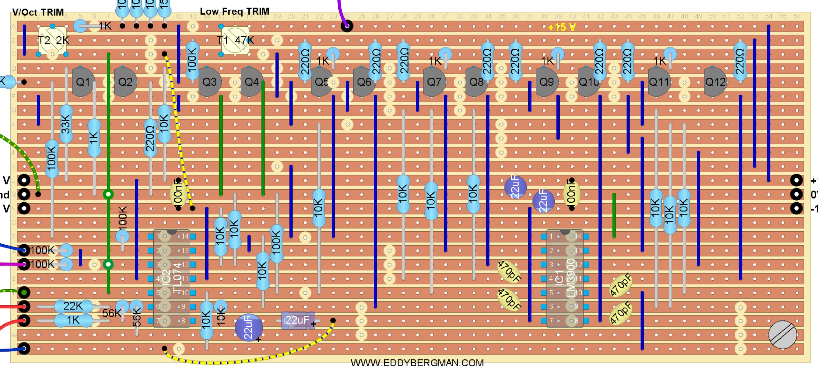
1. KOSMO SIZED LAYOUT:
Below here is the layout. I didn't put in the input jacks for the sync inputs or the output jacks for the wave forms and CV-OUT. It's already spaghetti junction and that would make it even worse. I assume you know how to hook up jack sockets. All potmeters are frontal view with shaft facing you. I have recently added 100nF decoupling capacitors directly between the IC's and 22µF electrolytic capacitors on the power rails, because this came up on Facebook. These are not included in the schematic drawing but they are in the original schematic in the PDF linked below. (You can use any value for the electrolytic caps between 10µF and a 100µF as long as they are rated for 25V or over.) There's an extra CV input marked on the layout. This is just incase you want to permanently connect something, like a sequencer, to the VCO and don't want to sacrifice an existing CV input for that. (If you don't need it, there's no need to include it.) 
Again I want to repeat what I said earlier: measure every components value before you solder it in. I always do this myself too because resistors and especially capacitors can be way out of spec sometimes and it is always best to be sure, especially when using cheap Chinese components. (I always use cheap resistors and they work just fine.)
I added and extra Hard Sync input to this layout recently. You can install a 3 way rotary switch for the Hard Sync and have some options this way. You can also leave it out, it's up to you. (The middle hard sync input comes from the Digisound 80 VCO Deluxe schematic.)
Here's the wiring diagram:


(Last revised: 18-Oct.-2020: Changed position of R18 from the wiper of the PWM potmeter to between the +15V and pin 1 of the PWM potmeter. I also changed the colour of the capacitors to be in line with other layouts and I made the wirebridges that connect to ground a green colour for clarity. 26-Nov.-2021: Removed striping from resistors added extra Hard Sync input. 18-Oct-2023: Colourcoded wirebridges.)

And here's a close-up of the stripboard. Don't forget to cut the copper strip underneath the 1M resistor above trimpot A. (Position A-31) The cut is difficult to see on the layout but it's there of course, otherwise the resistor wouldn't work. Also don't forget the jumpwire from that resistor to the wiper of trimpot C! (Position B-16 or 17). I made an extra layout with just the cuts and wirebridges, below.
Beware that some stripboards are sold with 56 instead of 55 holes horizontally. This layout is 55 holes wide. 
Stripboard only view:


Below an overview of the cuts and wirebridges seen from COMPONENT SIDE! As always, mark the cuts on the component side with a waterproof Sharpie and then stick a pin through the marked holes and mark them again on the copper side. Then you can make the cuts with a sharp hand held 6 or 7mm drill bit. Then lightly rub the copper strips with a fine grain sandpaper.
Cuts and wirebridges:


Bill of Materials.


(07-June-2020 Revised version. Numbering now follows numbering on schematic.)

Please note there's an extra Triangle to Sinewave converter stripboard you can add to the VCO, to give it a Sinewave output, at the bottom of this article!

2. EURORACK SIZED VERSION.
This version is the same as the above only the components are packed tighter together so the stripboard is only 40 holes wide which will make it fit behind a 14hp Eurorack panel.
A few resistor changes for use with a dual 12V powersupply have been made in this layout! The timing capacitor is the same 1nF as in the 15V version but in my build (further down the article) I used a 820pF cap. R11 was changed from 1M5 to 1M2, R23 was changed from 910 (or 1K) to 680­Ω. All the other changes I mention at the top of the article I left out to see if they were really necessary. In this case they weren't.
I also made a Eurorack layout which includes an alternative version for the Pulse Width Modulation input. You can input an external pulse width Control Voltage and still use the internal PWM potmeter too. Both CV's are summed in an opamp before being input in the AS3340 chip. That version is below this version.

Wiring diagram:

Stripboard only:

And the cuts and wirebridges.

Cuts only, component side. Mark the cuts first with a Sharpie on the component side and then stick a pin through the marked holes and mark them again on the copper side. Then cut away the copper at the marked positions with a sharp hand held 6 or 7mm drill bit.


The Bill of Materials 


3. KOSMO SIZE with ALTERNATIVE PWM INPUT.
I've had a request for an alternative solution for the pulsewidth modulation inputs. This person wanted to be able to have the pulse width connected to an LFO and still be able to control the pulse width on the panel as well. So I designed a little CV-mixer stage as an alternative for the standard PWM inputs. It requires an extra opamp but there is just enough room for that on the stripboard:

Here's the total view layout for this alternative version:


Stripboard only:

I tested this PWM setup in the Eurorack version below and it works perfectly. Make sure you make the extra cuts and wirebridges etc. I made an extra layout to help you with this:


Bill of materials for the above version with Pulse Width Modulation CV-mixer:


Schematic for this version:


4. EURORACK SIZED VERSION with ALTERNATIVE PWM INPUT MIXER.
I decided I had to also make a Eurorack version that included the above mentioned alternative pulse width modulation input mixer. So below is a layout that fits behind a 14hp Eurorack panel and includes the PWM mix input. I realized that I could actually do without one opamp in the PWM mixer section and that saved just enough space to make this layout size possible. You will notice that pins 1,2 and 3 of the TL072 are not used and that opamp is tied to ground.
A few resistor changes for use with a dual 12V powersupply have been made in this layout! The timing capacitor is the same 1nF as in the 15V version but in my build (further down the article) I used a 820pF cap. R11 was changed from 1M5 to 1M2, R23 was changed from 910 (or 1K) to 680­Ω. All the other changes I mention at the top of the article I left out to see if they were really necessary. In this case they weren't.
(Layout is verified.)

Wiring diagram:

Stripboard only:

Cuts and wirebridges:

Cuts seen from COMPONENT SIDE.
Mark the cuts first with a Sharpie on the component side and then stick a pin through the marked holes and mark them again on the copper side. Then cut away the copper at the marked positions with a sharp hand held 6 or 7mm drill bit.


And finally the Bill of Materials for this version:


SCHEMATIC:
Here's the schematic for this Eurorack version for dual 12V and with the PWM Mixer, made in KiCad by yours truly. 
With the component values shown here, this VCO runs excellently on +/-12V. It was very easy to tune too.

This schematic is an updated bi-polar version of the one I had here before. I added an offset trimmer so the squarewave can be trimmed to +/-5V instead of 0-10V. I used 470nF capacitors in series with the Triangle- and Sawtooth wave outputs to make them bi-polar too. I made PCB's of this version that are for sale in the webshop. (PCB Service in the Menu).

Before I had the PCB's I started building this version for myself on stripboard because I could use an extra VCO for my Eurorack system and of course I want to test these new layouts so I can verify them myself. I wired it all up and I can tell you that this layout is verified. It works like a charm. :) 
Mind you, the stripboard version is not bi-polar. It's 0-10V. But you can easily adapt it.


Faceplate all stocked ready for wiring up. It is 14hp wide (7cm) and the depth, when it was all finished, came to 4CM:


In the picture below you can see that all ground connections have been made with a bare copper wire, so only one ground wire will actually go to the ground on the stripboard. Do NOT rely on the metal of the faceplate alone to ground the sockets!! This will give you problems. Make sure all sockets are properly grounded to the stripboard like in the picture below.


The finished product. 


I did not use the Soft Sync option. I also left out the 1V/Oct output and the extra synchronization or tuner output that I put in my other Kosmo sized VCO's. There's no room for that here and I don't need it. The PWM mixer works remarkably well. You have full control over internal and external Pulse Width Modulation. The hard sync sounds great, especially the 'both' mode (middle input). It took a good 15 minutes to tune but then I had it in tune over 6 octaves at +/-8 cents over the entire range. That is a great result!
I used a 820pF polystyrene capacitor for C7 to be on the safe side when it came to tuning and this worked out really well. 

At first I just labelled the faceplate but I later made a new one this time using waterslide decals for the first time ever for me. It looks really good in the picture but there are some creases and it's a bit rough. So I still have some learning to do on this subject but the first result is encouraging.


THIS CONCLUDES THE DIFFERENT VERSIONS AND WE NOW CONTINUE DISCUSSING THE VERSION I BUILT FOR MY OWN MODULAR SYNTH. 
(The normal Kosmo sized VCO).
Below is a look at the finished stripboard. I soldered on a little copper eye to make mounting the stripboard on the particular panel I made easier, but there's room enough left on the stripboard to drill a few holes to mount it however you like. Make sure the copper traces are cut so no contact is made with the bolt and nut etc. In this picture you can also see the annoying little circle at the bottom of the AS3340 chip. Do NOT mistake this for the pin-1 indicator, and put the chip in the wrong way as I once did!! I had the chip mounted in the socket the wrong way around and had it switched on for about 20 seconds. It got so hot that I could smell it, that's what allerted me, and I switched it off immediately thinking the chip would be waisted but no, it survived! (They call that 'burning in the chip', LOL.  DON'T TRY IT!)


Here are the two identical VCOs side by side in my synth. You can see a 'Tuner' and 'Sync Out' output, which I added later on. More on that in the 'Synchronizing' section below:


About the CV-OUT connector:
You can see in the picture that I have CV-OUT jacks on the VCO's. These are simply in parallel over the 1V/Oct. input jack so I can daisy-chain more VCO's to one 1V/Oct. signal so that all VCO's receive the 1V/Oct signal from the Doepfer A-190-3 MIDI to CV converter. This is not included in the stripboard layouts but you can see it in the schematic drawing. 
If you use the Dual Buffered Multiple described on this website, then you don't have to include this CV OUT and you can spread the 1V/Oct. signal over all VCO's with the Multiple. But I do advise to include it. If you daisy-chain your oscillators like this you keep the Buffered Multiple free for other functions and you can daisy-chain upto 8 oscillators of this design before you'll get a slight drop in voltage in the 1V/Octave signal.

TURNING THE 0 TO +10Volt SIGNALS INTO -5V to +5Vpp SIGNALS:
Before I used the capacitor and offset method to make the VCO bi-polar, I made a little expansion board with 4 inputs and 4 outputs that gives you the option of giving a -5V offset voltage to the waveforms this VCO outputs and so turn them into bi-polar signals. This will make sure you can use this VCO with all the other projects on this website without the problem that the signals are 0-10Vpp. Most modules require signals that are -5/+5V peak-to-peak. This expansion board will provide that for you. You will have to find a way to implement this stripboard in your module design but if you're handy you will find a way. Anyway I leave that up to you. Here is the link to the expansion board project, Synthesizer Extra's No.4:

Synchronizing multiple VCO's:
I recently added two more outputs. One is parallel over the squarewave output socket and is used to connect the VCO to the negative Hard Sync of one of the other VCO's, so I can keep the Squarewave output free for normal use. The other output is in parallel over the triangle wave output and is used to connect the hacked Joyo tuner to the VCO, also to keep the Triangle output free for normal use. These outputs are not on any of the pictures or on any of the layouts but you can easily add them if you feel you need them. I find them very useful. If you want to synchronize two VCO's then just take a square- or sawtooth-wave out from the main VCO into the Negative Hard Sync input of the second VCO. 
The main function of the sync options on this VCO is actually not to have them track together but to create more interesting sounds. If you input a VCO signal into an other VCO's Hard or Soft Sync input you can get some really cool results if you change the frequency of the secondary VCO with the Octaves control potmeter. It will produce higher tones but the waveforms will be cut to the frequency of the synced VCO giving you all sorts of overtones and harmonic frequencies. If you never tried this I strongly recommend experimenting with this. (Also see the article about the Thomas Henry VCO-555 about synchronization). You will get that famous FM synth sound that can be really phat and rich in harmonics. 
The difference between Hard Sync and Soft Sync is that with hard sync de oscillator always resets the waveform when it receives a sync pulse. With soft sync it only resets the waveform if the slope of the incoming signal is within a percentage distance to the slope of the original signal. So it will ignore the sync signal unless the two oscillators (master and slave) are tuned close to some octave interval. With hard sync it doesn't matter, it will always force a reset and that's why it sounds harder and harsher. Negative, Both or Positive hard sync just determins if the waveform is reset on the negative going slope, both slopes or the positive going slope of the incoming signal. Funnily enough I never had much success with Positive Hardsync with this VCO design for some reason. Maybe I'm doing something wrong. On the Eurorack version it was the negative Hard Sync that wouldn't work LOL. Oh well.

Doepfer A-190-3V MIDI to CV converter:
In order for the VCO to produce actual notes we need to feed it with a control voltage that follows the 1Volt per Octave standard. For that we need a converter that turns the MIDI signals from a keyboard into a 1V/Oct CV signal. Now you can build a MIDI to CV converter yourself but I didn't trust myself to build one and I wanted the interface between the keyboard and the synthesizer to be absolutely fool-proof and reliable. So I bought my first Eurorack module: a DOEPFER A-190-3 MIDI to USB and CV converter and it was certainly worth the €130 I paid for it. You can connect any keyboard, that has a 5 pin  MIDI output, to it and it will output a 1V/Octave Control Voltage. It adds a Portamento (or Glide) function to the synth and besides the normal CV out it has 3 extra outputs for the modulation and pitch-bend wheels on the keyboard that you can connect to CV-2 for instance to get pitch-bend. It also has a Velocity output and a 'Learn' option on CV-4. It will assign CV4 to any mod wheel or knob that you touch on the keyboard. And it also has a USB input so I can connect the synth to my computer. Naturally it also produces a Gate signal for the Envelope Generator. The voltage of all the outputs can be set with jumpers on the circuit-board. I got the A-190-3V which is the Vintage edition which means the panel is black with white lettering to stay in keeping with the other panels in my synth. It's only 5 more euro's than the normal silver edition. I just made a 20cm high panel and cut a Eurorack sized hole in it. I first made it from cardboard so I could easily adjust the size of the hole and when it was ready I transferred it to an Aluminium panel and mounted the Doepfer in there. Then I made a special adapter cable to go from the Eurorack power system to the one I invented for my own synth. (See powersupply article).

OCTAVE SWITCH:
With VCO number four I changed the Octave potmeter for an octave switch, as an experiment. I used a 10 step rotary switch and I measured out a bunch of 10K resistors so I had 10 with the same resistance upto 10 Ohm accuracy. They were all 9K99. I soldered on the resistors in the way shown in the drawing below:


So you get 5 Octaves up and 4 Octaves down with a 10 step switch. If you want -5/+5 you'll need a 11 step switch, which you can easily find on eBay. This is more than enough though.
Now, this works but it is not the case that when you turn the switch you land on the exact same note as the previous Octave. To try and address that problem I exchanged the 10K resistor connected to -15V for a 10K multiturn potmeter, with a 2K resistor in series with it, going to -15V. Now it's not possible to tune it so it is spot on but I did manage to tune it so that each octave I go up, I can turn the Fine Tune one stripe up on the dial (decal) and I'm in tune. So you switch one Octave higher, you turn Finetune to the next stripe on the dial and you're bang on. And the same but backwards for switching down the octaves. This works well enough for me :) This will really only work well if you also have a hacked Joyo tuner connected to the VCO so you can see what you're doing.
To get this bang on the right note, you would need to experiment with the 3M3 resistor and try to buffer this potmeter and use really accurate resistors. So I wouldn't advise this switch solution, as it is presented here, for any serious project where everything needs to work perfectly. I'm just documenting it here because it is something I personally tried and want to keep a record of.

Here's a picture of the switch in the panel:


The output waves:
And finally a look at the waves this oscillator puts out. All nice clean waves as may be expected from the AS3340 chip but the ringing issue in the downward slope of the squarewave, which I mention in article 2 of this build series, is still there even in this design. Although it is significantly less prominent. This ringing must be common to this chip or something. Anyway, it's not audible so no real problem. I thought the zener diode over the squarewave output resistor might help to eliminate this problem but it has no influence but you can see from the pictures below that there are only a few spikes and only on the lowest notes. The picture below shows the ringing at note C1. Only 3 spikes! They only occur on the downward slope of the squarewave and they have a frequency of 28kHz so well above human hearing capabilities. BTW, I just found out that to get rid of this ringing you can connect a 1M resistor between pins 4 and 5 of the 3340 chip. But this is not implemented in the layout.


At note C3 there's only one spike left and after that it is completely clean. Maybe it adds to the character of the sound though. Who knows ^___^


Squarewave. You can see that the ringing is not even visible once you zoom out of the oscilloscope image:


Here's the ramp wave:


And this is the triangle wave:


Just for fun, here's a Triangle and a Ramp wave after being mixed together and after it's been through the dual Korg MS20 filter. You can see the high frequency resonance, produced by the filter, on parts of the wave form:


You can see that the output voltages are all around the +10 Volt except for the squarewave which is +13.4 Volt. I recently received a batch of 10 Volt Zener Diodes from China and I have soldered those in over the squarewave output and now all signal outputs are at the same 10Vpp level. Perfect!  You might have wondered why there is a 2K resistor (R22) in series with the squarewave output. Well, it's there to make the Zener-diode work. Zener-diodes always need a resistor in series with them for them to function as voltage regulators. The zener brings down the voltage from 13.4V to 10V so there's 3.4 Volt that has to be shaven off. That voltage is dropped over the 2K resistor and that's why it's there.

I made a little demo video showing the main features of this VCO. Sorry it's not very good, speech is not loud enough. Don't be fooled by the scope image, the signal really is 0 to +10Vpp but the scope measures the VCA output and that is -5/+5V. The VCA is also the cause for the slight rounding in the saw- and triangle waves. You can not hear that in the sound though. The VCA works fine. Btw, this video was made before I added the Sinewave option so that is not demonstrated here.
One other thing: Please keep in mind that this project and this demo video were made in the early stages of my synthesizer building career and thus I was not yet fully aware of everything you could do with a VCO in terms of using Synchronization and FM Modulation so therefor this demo is a bit basic.


TUNING THE VCO:
This VCO has 3 trimpots for tuning but we're only going to use 2 because the High Frequency Tracking or Linearity potmeter is not really effective for the lower octaves. So we leave that in the middle position. I have developed a tuning procedure of my own that is very simple and will get this VCO in tune over many octaves in less than 15 minutes.
If you don't have a useful tuner for calibration purposes but you do have a smart-phone then I recommend you download the 'Universal Tuner' app by Dmitry Pogrebnyak. This app can tune anything. Set it to the Chromatic Scale for tuning VCO's. It's available in the Google Play store for free. Of course any tuning app that displays frequency and notes will do. There's plenty to choose from. 
Before we start tuning, turn the Coarse Tune or Octaves potmeter off with the switch on the panel and set the Fine-Tune potmeter in the middle position. In the original text the wire connected to the wiper of the Fine Tune potmeter is de-soldered, but I recommend just leaving it in the middle position. Now turn the two trimpots all the way to one side until you hear it clicking. That means it's at the end. It doesn't matter which way you turn. Take a little screwdriver and turn trimpot A up about 3 quarters of the way (that's 22 turns). Now go to trimpot B and turn that up about 1 quarter of the way (That's about 7 turns. It's not necessary to be accurate with this and it also doesn't matter which way you turn them. It's just for setting a start position.)
If you want to be extra precise then let the VCO warm up for 15 minutes after turning it on so it can reach its normal operating temperature, before starting to tune it.

- Launch the Universal Tuner app. on your smartphone or use the tuner of your preference.
- Open up the 'Gain' potmeter on your VCA so you get continuous sound.
- Now press key C5 on your keyboard and turn Trimpot A until note C5 is in tune on your tuner.
- Now press key C2 on your keyboard and turn Trimpot B until C2  is in tune.
- C5 will now be out of tune again so press key C5 and retune it with Trimpot A.
- Now C2 will be out of tune again so press C2 and retune it with Trimpot B.
- Repeat these steps over and over until the VCO is in tune.
- You'll notice that you will need to turn the potmeters less and less to reach the C notes. After a few cycles of tuning they will be spot on their respective C notes.
- If you find that you need to turn the trimmers more and more to reach the C notes then switch potmeters and use A for C2 and B for C5
TIP: If you are tuning more than one VCO at once, make sure they are all switched on and all other modules in your modular synth are connected too otherwise the slight voltagedrop you get when you switch them all on can de-tune your VCO(s). Have them connected to the same powersupply that you intend to use for your modular system when you are tuning the VCO(s).

We tune with the Octaves control switched off to prevent variations in resistance from de-tuning our VCO. Having the wiper of the potmeter exactly in the middle results in 0V on the 1V/Oct. input so that would be the same as having the wiper disconnected by the switch, but not all potmeters are perfect and that's why we use the switch. Also because a little movement of this potmeter has a huge influence on the frequency. This is less important with the Frequency Fine control although you must make sure not to touch the fine control during tuning and make sure it stays in the 12 o'clock position during tuning.

Be precise with the final tuning. Check the exact frequencies of the C notes. The app I mentioned will display the note graphically and it shows the frequency. You can get it in tune to at least 1/10th of a Hertz although in my experience you don't have to go more than one figure behind the comma.

Here's a PDF about tuning 3340 VCO's that maybe of help to some of you if you have trouble tuning this VCO:  -- CLICK HERE --

Extra info for tuning on +/-12 Volt and using the V3340 chip:
As mentioned earlier, if you're running this VCO on +/-12V and you have trouble tuning it, change R4 from 200K to 270K or 300K. Someone kindly reported having trouble tuning this VCO on 12V and reported this as the solution in the comments below, so I thought I'd include it here. That's why the comments are so useful. If you come across problems like this please report it in the Eddy Bergman Facebook group or in the comment of an other article. (Comments for this article are closed because it got too long.)
I've also had a comment on Facebook about the V3340 chip not holding tracking when used in this circuit. I have no further details on that, but just so you know. It's recommended you use either the AS3340 or the CEM3340 chip.

It will usually be the case, when we start tuning, that the notes are too far apart rather than too close together and if you repeat the steps above and keep switching between C2 and C5 and using trimmer A for the high note and B for the low note, you will notice, as mentioned before,  that the notes get closer together and you'll have to turn the trimpots less and less to hit the right note. Eventually you will be spot on and the VCO will be in tune over at least 4 octaves. Be careful that you don't overshoot but you'll notice that soon enough if you have to turn the trimpots more and more to hit the right C note. In that case switch trimpots and use trimpot A for the low note and B for the high note.
You can of course use even higher octaves and other notes, like tune it between A2 and A7 for instance. I leave that up to you. I don't use C1 for tuning because it is so low my phone with the app has trouble tuning into it.
You'll get the hang of this tuning proces soon enough. It's really simple. It took me just 15 minutes after turning the VCO on to have it perfectly in tune, and when I say perfectly I mean perfectly! I was really chuffed about this ^____^

Here is a very interesting article that one of my readers sent to me. It deals with a tuning process for 12 Volt, using four trimmers which only need to be adjusted once, instead of going between two trimmers for ten or more times. I have not tested this methode but it's a very interesting approach so here's the link to the article:
https://cabintechglobal.com/tune3340


Here's a little overview of features and technical data about this VCO:

Frequency range:                    0.1Hz - 50kHz
Most accurate freq range:          5Hz - 10kHz
Waveform amplitude:                0V to +10Vpp
Octave adjust control range:     +/- 5 Octaves
Frequency Fine control range: +/- 0.5 Octaves
Positive- and Negative Hard Sync and Both.
Soft Sync
Linear Freq. Modulation input with level control.
Optional PWM input mixer that allows you to use an external Pulse Width Modulation Control Voltage and sum that to the internal Pulse Width control so you can have an external PWM CV signal coming in and still be able to use the internal PWM control.
The other (normal) CV inputs are in fact Exponential Freq. Modulation inputs.
CV-2 input with level control. (This is an Exp. Freq. Mod. input.)
Pulse Width Modulation both internally controlled and externally controllable.
Extra CV inputs can easily be added by using 100K resistors connected to pin 15 of the VCO chip. Measure the resistance of the 100K CV input resistors and make sure they are all the same, that way anything you connect to the inputs will be in tune right away.
All outputs are protected and can be short-circuited continuously without damage to any components.

Synchronization and FM input:
The positive Hard Sync synchronizes on the rising edge of a squarewave and negative H.S. on the falling edge. I'm getting excellent results with the Negative Hard Sync and Soft Sync. They all work fine and FM also gives great results. I personally use the negative Hard Sync input for syncing up two or more VCO's. I input a square- or ramp-wave from an other VCO into Neg H.S. and then they both react to pitch changes of the main VCO.  The FM input is also very cool to use. I can't describe how it sounds but if you build two of these and input one into the other and you turn the Octaves control back half an octave on the oscillator connected to the inputs, you're gonna get some great results. You can also input a Control Voltage from an LFO to get Vibrato or Tremelo effects. I demo this in the video.
Like I mentioned before, the normal CV inputs are equivalent to Exponential FM inputs. Try connecting the output of an other VCO to a CV input and change the octave of the input VCO upwards. Sounds pretty cool!

Finally and by request, here's a list of individual notes and their corresponding voltages, should you want to tune the VCO without a keyboard, using an accurate voltmeter. Ignore the 'Expo Output' column. It is not relevant to this VCO:


Here's a picture of VCO's one, two and three. The third one is installed at the top in the second case of the Bergman-Berlin synthesizer. I installed a Sinewave output too in VCO-3, but that was after this picture was taken. :)


The picture below shows the latest VCO, number four, and it now also has a Sinewave output!
Something many people have been asking me about for a long time, but now it's here. The design is too big to be included on the original VCO stripboard layout so I made it on a small piece of stripboard that can easily be added to the original print with a M3 bolt and a little stand-off tube. Read the paragraph below here for more on the Sinewave option.

Here's a picture of VCO number four with the sinewave output and two switches for Triangle and Sinewave with or without a +5V DC Offset. (No offset = +/-5Vpp, with offset = 0-10Vpp):


ADDING A SINEWAVE OUTPUT TO THE VCO:

I added the Sinewave option to the VCO waveforms by adding an extra bit of stripboard with a Triangle- to Sinewave converter, the design of which I took from the schematic of the Thomas Henry VCO Deluxe which you can find in the 'Files' section of the 'Synth DIY for non engineers Facebook Group'.  It's a very simple design so only needs a small piece of stripboard. I think you can easily figure out yourself the best way to add it to your specific VCO panel. I did not use the original Digisound 80 sinewave part of the VCO because it uses a CA3080 chip and there are a lot of fakes of that chip being sold. Anyway I tested that design and could not get it to work.
The Triangle- to Sinewave converter needs a Triangle input wave of +/-5Vpp and you can tap that straight from pin 12 of the TL074 Quad OpAmp chip on the main VCO stripboard. I have drawn an input socket on the layout but if you're building the converter into the VCO panel then just solder a wire straight from pin 12 of the TL074 on the VCO to the input of the sine converter. You can have two outputs for the Sinewave: a +/-5Vpp and a 0/+10Vpp one and you can use a switch like I did (see picture above) to choose which type you want or you can simply use two output sockets. A simple SPDT ON-ON Toggle switch will do fine. Solder each of the outputs to one of the top or bottom pins of the switch and then the output socket to the middle pin, making sure the outputs are nicely grounded the way it should be. You can tap the power supply straight from the VCO stripboard, that insures all the grounds are connected together like they should be.

I altered the feedback resistor (Rf on the layout) from 10K to 15K to get the amplitude correct with the other waveforms of the VCO. This had the effect that the +/-5V output got a negative DC-offset voltage which is why I put a 1µF electrolytic capacitor in series with the output of the +/-5Vpp sinewave with the minus pole towards the source of the sinewave. That resistor should really remain a 10K, but I found the higher amplitude more important. What I could have done, and may still do is change the other 10K that goes from the non-inverting input of the opamp to ground into a 15K also. Then everything is in balance again. Anyway, you should make sure the other two 10K's are matched and the transistors should also be matched. (Match them on hfe, that's good enough).
The output amplitude on a dual 12V powersupply is +/-4.2Vpp or 0 to 9.4Vpp. For a dual 15V power supply it is +/-5Vpp or 0 to 10Vpp.

Here's the layout of the Tri to Sine converter I installed in my VCO:


Triangle to Sinewave converter built into the VCO. This was my experimental stripboard so there's two TL072 opamps on there instead of the single TL074. As you can see, the VCO trimpots are still accessible:


Here's the schematic drawing. You can see I added a 1µF electrolithic cap on the +/-5V Sinewave output because I had a little negative offset voltage present there. See the text above the layout for the reason. If that solution doesn't help then you can use a cap on the output like I did.


Chapter three way back at the beginning of this synthesizer build series, deals with the Triangle to Sinewave converter and I have deleted the original article text and replaced the layout with this one because this one is much better and simpler. It works like a charm. That article also has pictures of the sinewave outputs.

NOTE: The VCO-Deluxe version with the tri- to sinewave converter and sub-oscillator all on the same print as the VCO, did not come through testing and I actually managed to blow up an AS3340 chip. So until I get new components for that project it's been put on ice for now. I'm actually concentrating on an other VCO design, without the 3340 chip (with sinewave option).

More extra's I added to VCO number four:
The panel I made for VCO number four is 2 centimeter less wide than the other 3 which are 10 CM wide. I included an output labelled 'Tuner' to which you can connect the JOYO Tuner after you hacked it. That is connected in parallel over the 10V Triangle output, soldered to the 5V/10V switch directly. (This is not included in any layout or schematic because it was a last minute addition to keep the normal outputs free.) As I mentioned earlier I later also added an extra output in parallel over the Squarewave output to connect the VCO to the negative Hard Sync of an other VCO so as to keep the regular output free for normal use.

Okay, that's it for this one. I hope this is useful to you. After searching for a good VCO design using the AS3340 chip it was a real relief to see that this VCO performed so well and was so easy to build and tune too. I wish I found an article like this one when I first set out to build my first VCO but now I've written one of my own I really hope it will help out all those of you who are building their own synthesizer, maybe for the first time, like me, and are looking for a good VCO design.
If you have any questions or suggestions you can go to the special Facebook Group for this website. I had to close the comment section for this article because it became too long but it is full of useful information so check through it and maybe the answer to your question is already in there. Otherwise, like mentioned before, you can post your question on the Facebook Group.
Share this article with your friends and follow this blog to keep informed of new posts. There are buttons for sharing on social media right below here.
Thank you for checking my website out and see you on the next one! :)

Here is a link to the original PDF file with all the text and schematics and tuning procedures for the Digisound 80 VCO: <click here to download or read the PDF file>


COMMENTS CLOSED FOR THIS ARTICLE.  Please comment in an other article or on the Eddy Bergman DIY Projects Discussion and Help Facebook group. The comments under this article have become so numerous that it was becoming impractical so I decided to close it. Sorry for the inconvenience. But they are a good source of information so read through them if you have any problems with the build. One other thing that came up recently: people trying to friend me on Facebook with a profile that is only a few minutes old with no pictures or info on it, get blocked by me for security reasons. If you have no FB, please use the comments of an other article to ask me questions.