The best version of the 7555 based ADSR's on this website. This one uses precision rectifiers to eliminate the problems the previous versions have. This project is small enough for Eurorack and runs fine on dual 12V or 15V and is easy to build even for beginners.
This is another version of the two 7555 ADSR's you've already seen on this website. The previous ones by Yusynth and Rene Schmitz had the problem that, because of diode voltage drop, the envelope wouldn't get down to 0 Volt after each cycle. The diode in series with the release potmeter would stop conducting when the voltage dropped to the threshold of 700mV in case of a 1N4148 and around 300mV for Schottky diodes.
This ADSR eliminates that problem.
By using precision rectifiers made up of a diode inside the feedback loop of an opamp, you solve the problem of the 700mVolt remaining after the release cycle and so the ADSR not returning to 0 Volt after each cycle. The opamp now has that voltage drop in the feedback loop and compensates for it, effectively creating a perfect diode.
I tried to address the voltage drop problem in the Rene Schmitz version by using Schottky diodes that have a very low voltage drop of about 0.3 V (300mV) and that already helped a lot. This version lowers that even further although on my oscilloscope I could still measure a tiny bit of voltage left over but the majority of that was due to the capacitor I was using. It was about 90mV. I used a normal electrolytic capacitor for testing. I then tried a Tantalum capacitor and that lowered the offset to around 10 to 20mV. That's almost the noise floor so really no problem what so ever. It's 35 times better than using a 1N4148 in the Yusynth ADSR. The reason for this is transistor resistance. The Gate voltage, if switched by a transistor, never reaches zero because of transistor resistance. But this is such a low voltage that you can totally ignore it. So please don't go fretting about 20 thousandths of a Volt. 20mV is equal to 0V!!
Use a 1µF Tantalum capacitor like the schematic says. The slowest risetime you can create with 1µF is 1.2 seconds. If you want longer risetimes you need to connect two caps to a switch so you switch between low and high speeds. That's up to you. I didn't include that option in this project but it's very easy to implement.
If you want to read more about this ADSR then here's the link to the Kassutronics webpage.
SCHEMATIC
I made some changes to the design of this ADSR. For one, I don't like the high value resistors on the gate input. I always get problems with the gate pulse not getting through. So because the Rene Schmitz version works so well I copied the Gate/Trigger section from that ADSR and put it in this one too. It's practically the same circuit but with different resistor values.
I also changed the inverted output to an attenuverted output. I find that much more useful because you can play with the attenuverter while you're feeding the ADSR signal into the CV input of a filter and get all sorts of cool sounds from it. You can turn it into a normal output if you need an extra output. Much more versatile I think. The schematic below has all the changes I made included.

Here's the KiCad version of the schematic. I'm teaching myself to work with KiCad and it's going very well. I taught myself in 3 days.

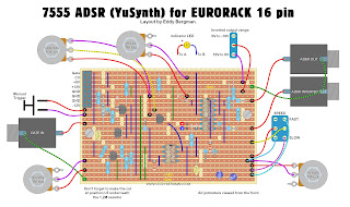
Below are the layouts I made for this project. As always they are verified. I used them to build my ADSR and it worked rightaway. An other hole in one.
I alterred the layouts a little one day after posting this article in so far that I added a transistor to drive the LED to avoid pulling down the envelope voltage.
Wiring: (All potmeters viewed from the backside!) As you can see the potmeter wiring is a bit complicated looking so be accurate when wiring up the pots!

Stripboard only:
If with testing you notice that the envelope doesn't come up when the Attack potmeter is fully closed then use a 330 Ω resistor in series with the Attack potmeter (R8) instead of the 100 Ω in the schematic. This is something I had to do with my build.

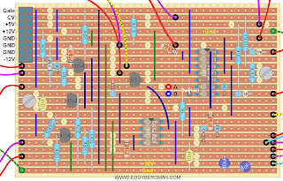
Cuts and wirebridges seen from the component side.
You know the drill, mark the cuts on the component side, stick a pin through the marked holes and mark them again on the copper side and then cut on the marks.

Here's the Bill of Materials.
Not every component is numbered exactly as in the schematic but most of the resistors are. Order a Tantalum capacitor for C3 1µF/35V. You can use any type of 7555 timer chip. I used the ICM7555. Don't use a normal NE555 though. It might work but they're not ideal. It needs to be a CMOS type.
As usual I didn't put any decoupling caps in but if you want to include it, there's room enough on the stripboard. You can put two 100nF caps; one from plus to ground and one from ground to minus. If you feel you need extra stabilization put some 10µF caps over the power rails too. That's up to you, the ADSR works fine without them.

PICTURES and test results:
This ADSR has a very fast risetime. I measured risetimes of 550µSeconds! The output amplitude of the envelope has a maximum voltage of 8.4 Volt when you run this on a +/-12 Volt power supply. Maximum Sustain level is 8 Volts. This is determined by pin 6 of the 7555 (Threshold) which stops charging the capacitor at 2/3rds of VDD. (+8V). The timer stops and the capacitor is discharged through the Decay potmeter and U2-D and D4 to the Sustain level. The output will stay at the Sustain level until the Gate input stops. Then the capacitor will discharge through the Release potmeter, U2-A and D3 to 0V. As I mentioned before, the maximum risetime of the Attack phase is 1.2 seconds with a 1µF cap. If you need longer times you can put a 1µF and a 10µF on a switch and connect that to the stripboard, so you have a choise. The fast times sound amazing though when used on filters (especially the 303 filter).
Here are some pictures of the finished product. They were taken in the test phase so some components that are on the layout are not in these pictures (like the LED driver transistor for instance).


I used the same faceplate as I used for my previous 7555 ADSR's. I just exchanged the stripboard for this one and wired everything up again.

Here are some screenshots from the oscilloscope. The first one shows the extremely fast risetime of this ADSR/ With Attack set to zero you can get risetimes of 550µSeconds. This with a Tantalum cap and a 330 Ω resistor in series with the Attack potmeter, instead of 100 Ω in the schematic.

Below is a screenshot of the quickest pulse I could get with all potmeters closed. You can see the risetime is the same as above, about 550µSec and the releasetime is faster because it only has 100 Ω in series. It's about 400µSec.Total time is 992µSec. So you could create a waveform with a top frequency of 1kHz with this ADSR.

Below here is the normal and inverted output. The voltages indicated by the scope are a bit lower because I had the LED connected straight to the output. I now have the LED driven by a transistor which means no voltage pull-down so the real maximum voltage is about 8.4 Volt. Max sustain voltage is 8 Volt as is the case with all ADSR's that use a 7555 and are run on +12V because that voltage is 2/3rds the voltage of the positive powerrails. If you run it on +/-15V it would be +10V.
The sustain is actually very stable because of the use of precision rectifiers. There is no leakage of voltage from the sustain stage.

Well, that is pretty much all I have to say about this. It was a pretty fast build, done on a sunday afternoon and because I re-used the faceplate and potmeters etc it wasn't that much work. I hope you enjoy building it. This is without doubt the best one of the three 7555 ADSR's on my website.
TIP: using your ADSR as a VCO. Send the squarewave output of a VCO to the Gate input of the ADSR. Now your ADSR acts as a VCO and with the Attack and Decay you can shape your own wave. It's a trick used in the Psy-Trance. This ADSR is fast enough to do this. I tried it and it sounds pretty cool when you then input it into a filter.
There is one more ADSR design that tries to really come down to zero volts after each cycle and that is the ADSR PRO by Davor Slamnig. You can visit his website by clicking here.
If you have any questions or remarks about this project then please put them in the comments below. Comments are moderated and don't appear straightaway!
You can also post your questions on the special facebook group for this website.