I seem to be building a lot of Yusynth designed circuits lately but that's because I know they work so well. This LFO is no exception. This is a medium difficulty project. I wouldn't advise it for beginners. Just take a look at the layout and you'll know what I mean.
This LFO circuit uses the well known ICM7555 chip as main oscillator and two TL074's (or TL084's or any other equivalent) to produce the different waveforms. The 7555 is the CMOS version of the NE555, Do NOT use an NE555 in this circuit!
The LFO has 4 outputs, one for Sine-, Triangle-, Squarewave and Ramp wave. It has a switch for two frequency ranges. The normal setting (x1.0) goes from about one cycle per 14 seconds to about 100Hz. Then there's a x0.1 setting that divides this roughly by ten so you get (in my case) one cycle per 60 seconds to 18Hz but this can be set with a trimmer on the print so you can set it to your own liking.
Because the layout is pretty chaotic looking, you need to go about this build very methodically. Mark out all the cuts you need to make first. I've made a special layout with just the cuts on it, to make it easier for you to do this accurately.
Because the layout is pretty chaotic looking, you need to go about this build very methodically. Mark out all the cuts you need to make first. I've made a special layout with just the cuts on it, to make it easier for you to do this accurately.
I must say I absolutely love this LFO. It has quickly become my goto LFO for modulation duties. It's particularly hand for modulating the LowPass Gate because the speed can be modulated with an ADSR for instance so a sound can start off sounding continuous with the LFO driven into audio range by the Envelope Generator and then lowering in frequency, fading out into a pulsating beat created by the Lowpass Gate. It's awesome :)
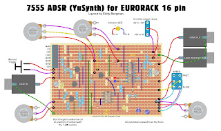
STRIPBOARD LAYOUTS:
Here's the stripboard layout I made for this LFO. I built mine using this layout so it's verified. All wire bridges connecting to ground are coloured green. Btw, you can use other values for the 50K panel potmeter. It's just a voltage divider level pot. You can use 10K or 100K or 1M, whatever you have available.
Naturally, instead of having a switch to go between Saw and Inverted Saw (Rampwave) you can install two output sockets and have both available at once. That's up to you.
Instead of the 50K resistor at the top right, you can use a 47K one.
Wiring diagram:

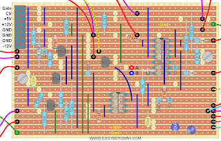
Print only. Beware that some stripboards are sold with 56 instead of 55 holes horizontally. The layout is 55 holes wide:

Here's the overview of where the cuts need to be made. I usually mark them with a black Sharpie on the component side, because that way they are easier to identify from the layout, and then I stick a pin through the marked holes and mark them again on the copper side. (That's why I'm showing both sides here). Then I cut the copper side with a 6mm or 7mm drill bit (or a Dremel-tool) in the marked places.

Bill of Materials:

Here's the schematic I used for the layout:

You can see in the schematic that there's a fifth output, underneath the saw output. This is an inverted version of the sawtooth wave and I installed an extra switch to give you the choise between Saw or Ramp. (The un-inverted version is actually a Ramp (rising voltage) and not a Saw, but whatever.)
All waveforms are bi-polar, they have the zero volt line as their mid point so they have a negative and positive phase.
Here is the result of some measurements I took from the LFO:
In the x1.0 setting:
Frequency Range = 1 cycle per 14 seconds to 100Hz
Squarewave amplitude = +5 to -5 V. Duty Cycle = 26% to 86%
Sinewave amplitude = +5.3 to -5.3 V
Triangle wave = +7 to -7 V
Sawtooth wave = +7 to -8 V
In the x0.1 setting:
Frequency Range = 1 cycle per 60 seconds to 18,7Hz
Amplitudes are the same.
Squarewave duty cycle = 18% to 98%
The synchronization pulse threshold = +2,9V.
As you can see, a fantastically broad range of options and synchronization works very well. When you put a high amplitude sawtooth wave on the CV input the resulting frequency sweep can reach well in to the 400Hz (in x1.0 setting). The LED indicates the frequency rate and is connected to the squarewave output so it will react to changes in duty cycle by being on longer or shorter.
Calibrating the circuit:
You can set the Frequency range by turning the Rate panel potmeter all the way counter clockwise and then use trimmer T1 to set the lowest rate.
Trimmer T2a and T2b are used to set the sawtooth wave in such a way that the positive phase has the same amplitude as the negative phase. In other words you set it so the zero volt line runs right through the middle of the wave. There are two of them because one is used in the x1.0 setting and the other in the x0.1 setting, so only one of those trimmers is active at any one time. Therefore you need to set this twice.
Trimmer T3 is used to set the Sine symmetry. Turn it so that the top of the wave has the same curve as the bottom of the sinewave. This potmeter also influences the duty cycle of the square wave, so you need to set the duty cycle panel potmeter in the middle position and trim the Sinewave so it looks good and then look at the Squarewave and make sure the panel potmeter for duty cycle can be used over its full throw. To make things even more complicated, this trimmer also has an effect on the shape of the Triangle wave so it's a bit fiddly but you need to go between all of these three parameters and find the right setting. You'll get the hang of this soon enough though. It sounds more difficult than it really is. You just have to find the setting that looks the best for all three waveforms. A multi channel oscilloscope will be of great use here.
If you can not get the waveforms right you need to change the 1µF and 10µF capacitors for some other ones with the same value. Yusynth says to use Tantalum caps here but I tried those and it only made things worse. But you may have a different experience. You need to be able to experiment, an other reason why this is not a beginners project.
Here are some screenshots of the waveforms. You will need to try and trim the negative spike in the top of the Triangle wave away while keeping the sinewave looking good. I don't think it's possible to get rid of it completely but you won't hear it in normal use.
Wiring diagram:


Bill of Materials:

Here's the schematic I used for the layout:

You can see in the schematic that there's a fifth output, underneath the saw output. This is an inverted version of the sawtooth wave and I installed an extra switch to give you the choise between Saw or Ramp. (The un-inverted version is actually a Ramp (rising voltage) and not a Saw, but whatever.)
All waveforms are bi-polar, they have the zero volt line as their mid point so they have a negative and positive phase.
Here is the result of some measurements I took from the LFO:
In the x1.0 setting:
Frequency Range = 1 cycle per 14 seconds to 100Hz
Squarewave amplitude = +5 to -5 V. Duty Cycle = 26% to 86%
Sinewave amplitude = +5.3 to -5.3 V
Triangle wave = +7 to -7 V
Sawtooth wave = +7 to -8 V
In the x0.1 setting:
Frequency Range = 1 cycle per 60 seconds to 18,7Hz
Amplitudes are the same.
Squarewave duty cycle = 18% to 98%
The synchronization pulse threshold = +2,9V.
As you can see, a fantastically broad range of options and synchronization works very well. When you put a high amplitude sawtooth wave on the CV input the resulting frequency sweep can reach well in to the 400Hz (in x1.0 setting). The LED indicates the frequency rate and is connected to the squarewave output so it will react to changes in duty cycle by being on longer or shorter.
Calibrating the circuit:
You can set the Frequency range by turning the Rate panel potmeter all the way counter clockwise and then use trimmer T1 to set the lowest rate.
Trimmer T2a and T2b are used to set the sawtooth wave in such a way that the positive phase has the same amplitude as the negative phase. In other words you set it so the zero volt line runs right through the middle of the wave. There are two of them because one is used in the x1.0 setting and the other in the x0.1 setting, so only one of those trimmers is active at any one time. Therefore you need to set this twice.
Trimmer T3 is used to set the Sine symmetry. Turn it so that the top of the wave has the same curve as the bottom of the sinewave. This potmeter also influences the duty cycle of the square wave, so you need to set the duty cycle panel potmeter in the middle position and trim the Sinewave so it looks good and then look at the Squarewave and make sure the panel potmeter for duty cycle can be used over its full throw. To make things even more complicated, this trimmer also has an effect on the shape of the Triangle wave so it's a bit fiddly but you need to go between all of these three parameters and find the right setting. You'll get the hang of this soon enough though. It sounds more difficult than it really is. You just have to find the setting that looks the best for all three waveforms. A multi channel oscilloscope will be of great use here.
If you can not get the waveforms right you need to change the 1µF and 10µF capacitors for some other ones with the same value. Yusynth says to use Tantalum caps here but I tried those and it only made things worse. But you may have a different experience. You need to be able to experiment, an other reason why this is not a beginners project.
One other thing which I became aware of through reader feedback; if your output levels are very low and transistor Q1 gets hot then you might be using fake chips. I've had feedback where this problem turned up and changing the chips for ones from a reputable source fixed the problem. So once again, make sure your chips aren't fakes from China.
The x1.0 and x0.1 frequency range settings.
Calibrate the LFO in the frequency setting that you think you will be using most. If you get the waveforms right in the x1.0 setting then the sinewave may not look ok in the x0.1 setting. That's a little quirck of this LFO and difficult to get right but I usually only use an LFO in the 10 second to 10Hz range, so if all is well in the x1.0 setting, then that's good enough for me. The duty cycle range of the squarewave varies too, according to how the frequency range switch is set. It's really only the sinewave that I personally can not get right in the lower frequency setting. It rises normally and then drops off so it's more like a sine version of the ramp wave. But that's the only thing I can't get right. I found that adding a 0,1µF electrolithic capacitor in parallel over the 1µF cap helps in getting it all looking good. This however will vary from build to build with component tolerances etc.
12V vs 15V:
This LFO will work on a dual 12V powersupply but the frequency will go down by a large amount but you can turn that up again with the trimmer T1 on the print. The amplitudes of the waveforms will go down to between 2 and 5 Volt so that is significantly lower. The LFO is not really meant to work on +/-12V but it will work. However, if you need to address this problem I advise to make an extra print with a TL074 quad opamp chip and set these opamps to a gain of 2 and have all the waveforms go through it. That will double their amplitudes. You can also give them a DC offset voltage to keep them all at a positive voltage if that's what you need. However, if you're a beginner and don't know how to do the above mentioned extra's then don't worry. Don't bother with it for now. Just build the LFO and run it on 12V. LFO outputs are usually attenuated anyway so the lower amplitude signals will still be very useable. This will be a module you will use a lot! I guarantee it.
Here are some screenshots of the waveforms. You will need to try and trim the negative spike in the top of the Triangle wave away while keeping the sinewave looking good. I don't think it's possible to get rid of it completely but you won't hear it in normal use.
As you can see from the screenshots this is a bi-polar LFO. Meaning the output voltages go both positive and negative.


Here's what happens when you put an inverted ramp wave (from high to low) on the FM Modulation input (CV IN). You get a frequency sweep that can be quite high in frequency, but you can set the level, and with it the maximum frequency, with the FM Level potmeter. You can see that the amplitude drops a bit in the higher frequencies for some of the waveforms:

Some pictures of the finished module:


I am thinking of adding a second print, like I mentioned earlier, with just a single TL074 on it to use the 4 opamps to give the 4 waveforms a +5V DC offset so they go from 0 to 10V and stay in the positive voltage range. Edit: There's now a Dual Voltage Processor project on this website that can be used for this purpose too.
To conclude this article I made a little test video showing off the 'Synchronization' feature of this LFO, which was the main reason I wanted to include it in my modular synth. As you can see it works very well:
Here's a Falstad simulation of this circuit which I drew myself. It's not working quite like it should but it gives a good indication of how the circuit works: -- CLICK HERE --


The result of introducing the synchronization pulse. The waveform resets at the rising edge of the sync pulse and will remain high until the pulse falls away. Short trigger pulses will work best here:

Here's what happens when you put an inverted ramp wave (from high to low) on the FM Modulation input (CV IN). You get a frequency sweep that can be quite high in frequency, but you can set the level, and with it the maximum frequency, with the FM Level potmeter. You can see that the amplitude drops a bit in the higher frequencies for some of the waveforms:

Some pictures of the finished module:


I am thinking of adding a second print, like I mentioned earlier, with just a single TL074 on it to use the 4 opamps to give the 4 waveforms a +5V DC offset so they go from 0 to 10V and stay in the positive voltage range. Edit: There's now a Dual Voltage Processor project on this website that can be used for this purpose too.
To conclude this article I made a little test video showing off the 'Synchronization' feature of this LFO, which was the main reason I wanted to include it in my modular synth. As you can see it works very well:
Here's a Falstad simulation of this circuit which I drew myself. It's not working quite like it should but it gives a good indication of how the circuit works: -- CLICK HERE --
Okay that's article number 30 done! Quite a milestone for me I must say, to write 30 articles in so short a time. As per usual, please put any remarks or questions in the comments below, or post them in the Facebook Group for this website.