Showing posts with label curve. Show all posts

Saturday, 21 March 2020

Synthesizer Build part-24: ADSR with 7555 (YuSynth design)

A great ADSR. Works very well and it's a very simple design, no trimmers to set. With verified stripboard layouts and now also in Eurorack format. There are also Eurorack Gerber files available for download for this project.

NB: Although I rate this as one of the best DIY ADSR's out there, there are some people having problems with this design. Even in my module the LED does stay on very dimly. Other people report problems with the envelope not returning to 0 Volt. In my case it works okay but I want you to be aware of this before you decide to build this. Should you have doubts then there is now an alternative to build.
Project 67, the Kassutronics Precision ADSR It also uses a 7555 chip, comes in eurorack size and works like a charm.

What does an ADSR or Envelope Generator do?
The Envelope Generator is generally better known as the ADSR which stands for Attack, Decay, Sustain and Release. These are the four amplitude phases a note goes through when you press a key on the keyboard. If we didn't have this ADSR in combination with the VCA, we would constantly hear the oscillator sound but we only want to hear it when we press a key on the keyboard right? So as soon as a key is pressed down, a Gate signal goes into this ADSR to tell it to produce an Envelope Signal. This envelope signal then goes to the VCA (Voltage Controlled Amplifier) where it opens up the VCA and so the amplitude of the envelope signal determins the volume of the sound coming out of the VCA.
The attack is the speed of the initial rise of the note, when you first press the key. Set it to zero and the sound is instantly there. Turn it open and the sound is going to take a while until it gets to full volume.
Decay is the time it takes for the note to go from the peak attack level to the sustain level. 
Sustain is the level of the note as you keep the key pressed down. It is usually set a bit less loud than the peak Attack level. (If we set Sustain fully open it will be on the same level as the peak Attack level and then it won't matter how you set the Decay because there's nothing to decay to.)
Then we have Release and that is the amount of time it takes for the note to fade out once you let go of the key. So the envelope generator produces a signal that determines the volume of the note over time and this signal is being used by the Voltage Controlled Amplifier (VCA) which interprets it as an output level. In some Minimoog synths it is also called the Loudness Contour.
Now of course the envelope output is a control voltage so it doesn't mean that you need to use it for the above mentioned purpose. You can connect it to anything that can be controlled with a control voltage like the filter cut-off or the pulse width of a squarewave or even the pitch of an oscillator. This opens up a miriad of options but let's not get ahead of ourselves here. If you're just starting out with synth building, you need the ADSR to open the VCA and the fancy stuff will come automatically with more experience. And this ADSR is great for beginners but also for seasoned builders in need of a good working ADSR. This is my ADSR of choise really.

My building experience:
This is the fourth Envelope Generator I present on my website and I think this one is the first that worked as it should straight away. No trimmers to set in the circuit either. I just used the schematic from the Yusynth website made a layout and built it. On the website he has two versions, an old and a new one. I built the new one. I can say without any doubt that this design is perfect if you want a good and reliable ADSR to pair with your VCA or to drive a filter. And because the circuit is so simple, even a stripboard version like this one would be robust enough to put in a rig you take on tour with you because, providing the panel is sturdy enough, there's practically nothing that can go wrong on the circuitboard.

This is the schematic. The opamp numbering on the schematic is different on the layout, I used the opamps in a different order but it works the same.


And this is the stripboard layout I made for it. It is verified, I used it for my build and it worked first time. Because it's so simple a design I didn't even test the stripboard after building it. I made a frontpanel and wired everything up and then I plugged it into my synth and it just worked. I would advise to change the 1M resistor (R6) on the Gate input, from a 1M type to a 100K type right from the start. Might save you some troubleshooting later on.


You can see the components are rather stretched out over the stripboard. This is something I did in all my early projects to make troubleshooting easier. There's a smaller version further down this article that can also be used for Eurorack systems. (There are also Gerber files for a Eurorack version available at the bottom of the article.)
Here is the stripboard only view: 


Bill of Materials:


If you want to add some extra outputs with buffers then below here is an extra layout that you can add to the ADSR to provide you with two extra normal outputs and two inverted ones. Of course you don't need to use the inverted output signal, you can use all four outputs for the normal signal. It doesn't matter what kind of signal is presented on the inputs, it will be replicated on the two outputs. (Two outputs for each input). This is an all purpose design so you can use this board for anything you like, even other projects like VCO's.


The wiring of the potmeters may look a bit strange with pin 3 left unused on three of the four potmeters, but I assure you that this is the way it should be wired up. Just follow the layout. It'll work fine I promise you. You can see in the schematic drawing that these pins are left dangling in the wind so that's what we do.
The ADSR triggers with a gate signal with a threshold of 3 Volt. The output envelope is 10Vpp. There's a manual trigger button on the panel (which is useful for testing). The envelope generator has two outputs. There's a normal output and an inverted output with a switch that lets you choose between +10V to 0V or 0V to -10V. There's also a switch to change the duration times with 'Fast' and 'Slow' settings. Use a DPDT ON-ON switch for the Fast/Slow function and a SPDT (ON-ON) switch for the Inverter voltage function. In Fast mode the duration for Attack, Decay and Release can be set between 1mS and 1Sec. In Slow mode they can be set from 5mS to 10Sec. These times are generated by the 1µF and 10µF electrolytic capacitors C4a and C4b. In the text on the Yusynth website it says to use Tantalum caps for this but I used normal Electrolithic Caps and this works just fine. I hate Tantalum caps anyway, they always blow up on me, LOL. If you want longer times you can install bigger caps. You could even take a 3 position switch and add a third cap of, for instance, 47µF to generate really long times. I haven't tried this myself so I can not guarantee it works but I don't see why it shouldn't.
There's a LED to indicate the level of the envelope. The LED remains lit very dimly if there's no Gate signal present and the ADSR is at rest. This is normal for this circuit. It simply indicates the ADSR is ready to fire.
Make sure you use three logarithmic 1 Mega Ohm potmeters for Attack, Decay and Release. Otherwise it will be difficult to set the parameters accurately. For Sustain we use a normal linear 10K potmeter.
It's interesting to note that all the 1 Mega Ohm potmeters control time parameters (Attack time, Decay time and Release time) while the 10K linear potmeter controls a level. The Sustain level.
You can run this envelope generator on a dual 12 Volt powersupply without any changes only the envelope output levels will go from 0 to 8 Volt instead of 0 to 10 Volt.
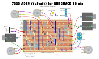
EURORACK LAYOUTS:
I recently made layouts for Eurorack in both the 10 pin and the 16 pin versions. In the 16 pin version the Gate input is connected to the eurorack-connector's gate pin but also has a separate input socket. If you want to disconnect the Gate signal from the eurorack-connector if you're using the normal input socket, then you must solder the gate connection from the eurorack-connector to the switch of the gate input socket instead of using the wirebridge as shown on the layout for the 16 pin version.
(Remember there are also eurorack Gerber files available at the bottom of this article.)
I've had confirmation that this layout works. So it is now officially verified.

Eurorack 10 pin version:
A very observant reader drew my attention to the fact I had forgotten the connection from pin 6 of the 7555 to pin 14 of the TL074 so I had to tuck that in later and that's why it runs underneath the chip socket of the TL074.  You can also choose to make that connection directly on the backside (copper side) by soldering a small wire inbetween those points, that's up to you.
I used Schottky diodes in this design because that works much better. I advise to always use Schottky diodes in Envelope Generators because it will help with cutting down any DC offset voltage at the output.
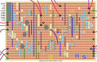

Stripboard only:


Cuts and wirebridges seen from component side. Mark the cuts on the component side with a black Sharpie or Edding pen and then stick a pin through the marked holes and mark them again on the copper side. Then cut the strips at the marked positions with a sharp hand held 6- or 7mm drill bit.


Bill of materials, will also work for 16 pin version except you must use a 16 pin Eurorack power connector obviously ;)


Eurorack 16 pin version. The diodes are marked as 1N4148 in the layouts below but use Schottky diodes instead! Like mentioned in the 10 pin version and the BOM above.


Stripboard only:


Here are some screen shots from the oscilloscope. These are from the 'Kosmo' sized ADSR but that shouldn't matter in the end result of course:

The normal envelope:

Inverted 0V to -10V:

Inverted +10V to 0V:

Here's a image showing the fastest rise time this ADSR can reach. It's just under 1 milliSecond or 980µSec.


TROUBLESHOOTING:
If you experience problems with this ADSR like the LED is always on and the VCA does not close then here are some tips for you suggested by people in the comments and on the Facebook group.:
Put a 100 Ohm resistor in series with diodes D4 and D2 (to the release and decay potmeters)
Put a 4K7 resistor in series with the LED. (This didn't help for me, my LED is always a tiny bit on)
Replace all 1N4148 diodes for schottky diodes.
Reduce the value of C3 from 10nF to 4,7nF or even 1nF.
Use a 500K potmeter for Release if you have trouble accurately setting the release time.
Replace the 1M resistor R6 with a 100K resistor. R6 is located at the Gate input


Well, that's all there is to say about this project really. A very satisfying build because everything worked as it should right from the start. The panel potmeters work over their complete throw, unlike some other E.G.'s I built, and you can set all the parameters very easily. If someone would ask me what ADSR to build I would certainly recommend this one. You can easily add on extra outputs if you so desire. You can add a TL074 for instance and wire up some extra outputs and/or inverted outputs. That's easy enough to do.
Okay, to close off, here are some pictures of the finished product. I made a copper bracket to keep the print in place behind the panel. That way I could use just one M3 bolt. I soldered all wires straight to the copper side.


Finally: there are now Gerber files available for this particular module (for Eurorack) which I uploaded to MediaFire from where you can download them for free. 
Just click here: --- DOWNLOAD GERBERS ---

EURORACK VERSION WITH LOOPING OPTION:
Now there's also a Eurorack version of this ADSR that has a looping function included. Paul Darlington, a member of the EB Facebook group, came up with this brilliant addition to the schematic. Here's a link to the files he posted on Github: --- CLICK HERE ---
You are not allowed to use these files for commercial purposes! They are published under Creative Commons 4.0 license. 
Here's a picture of the faceplate of Paul's ADSR module:


Okay, that's all for this article. If you have any questions or comments please leave them in the comments below or post them on the special Facebook Group for this website.


Sunday, 18 June 2017

Simple but effective Transistor Curve Tracer circuit.

This curve-tracer uses only 6 transistors and produces a beautiful curve display on an oscilloscope in X-Y mode. And it doesn't even matter which transistors you use to build it with!! I build it up on a bread-board first and it works very well! The component that is being tested does not get hot, unlike some Chinese Curve Tracers. 
I was impressed by the simplicity and effectiveness of this little circuit and since I didn't see it available on the internet I thought I'd share it with the world.
Here is the circuit:
(At the bottom of this article there's an improved version of this design.)

This circuit can handle all sorts of components, NPN transistors (bi-polar junction transistors), diodes etc. However it does not work with FET transistors, like Jfet's, P or N channel mosfets etc. You can build a PNP version of this circuit. Instructions for that are at the bottom of this article. As you can see, very simple design.  
The traces are displayed from right to left which is the wrong way around for a normal graph display but you can change that by inverting the X channel on your scope. However most analog scopes won't allow you to invert the X-channel, usually only the Y-channel, so you'll just have to get used to that. That's what you get with such a simple design. (The graph for the PNP version requires you to invert the Y-channel (channel-2) on your scope, so that will look normal on almost any scope.)
TUT is the Transistor Under Test, TUN stands for Transistor Universal NPN, TUP is Transistor Universal PNP and DUG stands for Diode Universal Germanium. I used a AA119 for the diode, but I would advise you to use a Schottky Diode instead. I tried it with a 1N5819 and that works just as well as a Germanium diode. 
For the NPN's I used the 2N3904's (I also tried the BC547 and it works just as well) and for the TUP I used a BC559. I set it all up on a bread-board and it worked like a charm.
The circuit diagram advises a power supply voltage of 6 Volt but I use it with 10 Volt and I feel that works better. You can turn the voltage up to 15 Volt without any problems. I haven't tried higher voltages then 15V but I think the voltage is only limited by the transistors you use in the circuit and a higher supply voltage gives you more data about the transistor under test. As to power consumption: it hardly uses any power at all. At 6 Volt it draws a current of 4.8 mAmps and at 15 Volt 11.8 mAmps. That's equivalent to 0.177 Watts.

A reader of mine kindly sent in a link to a Falstad animation that shows how the step generator actually works which is very interesting to see. Here's the link so you can have a look for yourself:
- Click here for circuit animation -

The number of traces that appear on the screen is determined by the ratio between C5 and C4 and can be varied by changing the value of C4. A higher value will take longer to discharge creating more steps inbetween fully charged and fully discharged. Don't change C5 because that will change the length of the traces. Using a 2N3904 as test transistor, with a 68nF capacitor for C4 I got 5 traces on the screen and with an 82nF I got 6 traces. It also changes if you vary the power supply voltage. Depending on the type of transistor under test you can loose a trace if you turn the voltage up above a certain value. For instance with the AC187 under test, the display goes from 5 to 4 traces if the voltage goes above 11.4 Volt. Btw, should you ever short circuit this thing and it doesn't work any more, your best bet is to replace T4 and T5, They are the first components to go. Believe me, I speak from experience ^____^
One more thing: make sure the ground of the oscilloscope is NOT connected to the ground of the powersupply. Otherwise this circuit won't work, you'll short out the transistor under test.

Here are some tips on how to set your digital scope (in my case the the Rigol DS1054Z) for best possible display of the curves:

1. Set your scope into X-Y Mode.
2. Put your probes on DC coupling so you can measure voltages with the cursors of your scope.
3. Set the bandwidth limit for both probes to 20MHz
4. Invert Channel 1 probe.
5. Set the horizontal timeline to 2.00mSec/Div
6. Set both probes to 1x multiplication (and don't forget to set it in the scope to 1x aswell)
    1x will give you sharper lines but if you want to do measurements it's better to put the probes at 10x to reduce the influence of the scopes impedance on the resistance in the circuit.
7. Set channel 1 (X) to 1 Volt/Division
8. Set channel 2 (Y) to 500 mVolt/Division
9. Go into the 'Acquire' menu and set the Memory Depth to 60K

This gives a good starting point from which you can fine-tune your scope depending on the type of transistor you are testing.

With these settings you should get a picture like this one:


This is what the graph from an NE555 based curve tracer looks like. You can see the lines are a tiny bit thicker although the difference is almost negligible.


You can also measure diodes with this circuit. Just put them between the emitter and collector of the TUT (Transistor Under Test) points and you'll get the characteristic diode curve. The anode must be connected to the collector and cathode to the emitter clip.

Here is a picture of the PCB layout including the parts list and a picture of how the curve appears on an analog scope:


I've posted a video about this circuit on my YouTube channel which you can watch below. The video description contains a link to the original article, written in Dutch, of which I made a PDF file which you can download for free. That link is also posted at the bottom of this article. I recently found an English language version of this same article on Archive.org and that link is also at the bottom of this article. If you plan on making this circuitboard then beware of the transistor polarity! The layout used in this article was designed for transistors like the BC547 with Collector on the left and Emitter on the right so if you plan on using the 2N3904 the Collector and Emitter will be reversed so you must put those in the other way around.
In the video the traces are displayed pointing the wrong way, namely to the left. This is because at the time of filming I hadn't figured out yet that you could invert channel 1 to get it pointing in the right direction.


This circuit makes your oscilloscope an even more useful instrument than it already is because it allows you to easily match transistors together, which is sometimes necessary if you're building a high quality audio amplifier or a precision oscillator or for high accuracy current mirrors or if you (like me) are building your own synthesizer and need matched pairs of transistors for the filters (like the famous Moog Ladder Filter).
In the video I made the remark 'it's not that accurate of course because it's a very simple design' but I was thinking about that and that is actually a bit nonsensical because the oscilloscope doesn't lie. In fact this circuit is as accurate as your scope is and using the cursors you can make some very accurate measurements and calculate all sorts of parameters from these traces.

I've done some more experimenting and I've designed my own PCB with my own design layout. The new circuitboard has a lot of surface area for mounting clips to put the transistor under test in. I simply made some small coils out of copper wire and soldered them to the circuitboard. It works very well. I made the PCB so that it has a big ground plane, to reduce noise and it seems to have done the trick because I get nice thin/sharp lines when the curves are displayed on the scope. The breadboard versions always had thicker lines, at least on a digital scope. Recently I've also soldered on some short wires with alligator clips so I can easily measure big power transistors like the 2N3055 in TO-3 housing.
Here are some pictures of the new PCB. It doesn't look very professional because I simply draw the circuit layout straight onto the board with a permanent marker and then etch it. This is a double sided board:


Some screenshots showing the curves I get from this new circuitboard:
This is the curve from a 2N3904:


This is the curve from an AC187 Germanium Transistor. You can see that the back-traces are very prominent. That's also a drawback of the simple design. However it doesn't matter because all the information you can get from a graph like this is easily visible, plus you can dial it down a bit if you have a scope with an intensity graded display. The improved version at the bottom of this article eliminates those back traces


This is an AC176 Germanium transistor and at the top you can see the different wave-forms that make up the curves in the X-Y display. The yellow signal is from the X-axis (horizontal) and the blue from the Y-axis (vertical):


Below is the curve of a PNP transistor. The OC79 Germanium PNP transistor to be precise. So if you see a curve like this, you know your transistor is a PNP type and should be measured with the PNP version of this circuit. Notice how the wave-forms have changed. The blue Y-axis signal has changed from a square-wave to a Shark Fin wave.


This next curve is from a BC547.
Now we can do some calculations on this with the help of our cursors and determine the Collector current of the middle trace for instance. We select the 'Cursors' on our scope and set the first horizontal cursor on the middle trace and the second on the 0 Volt line. The readout of cursor AY says we are at 1.45 Volts. We know the collector resistor (R7 in the circuit) has a value of 330 Ohms so the current through that resistor and therefore also through the Collector of the transistor is 1.45/330=4.39 mA.


CALCULATING HFE:
If we now want to calculate the Hfe or Beta or amplification factor of this transistor, at this value, we need to know the Base current. The Base current is biased through resistor R8 which is 270K. I soldered some copper-wire to each end of R8 so I could connect a probe to it. That's the purple waveform in the picture below. The probe we use to measure the voltage drop over R8 has an impedance of 10MOhm so the total resistance of R8 will drop to 262.9K.
The image below shows the voltage drop over R8 which is 3.64 Volt. If we divide that by 262900 Ohm we get 13.8 µAmpere. Hfe is then Ice/Ibe = 0.00439/0.0000138=318.1 for the middle trace.
From these curves you can also get a rough indication of the collector/emitter impedance; the flatter the horizontal bit of the trace is, the higher the impedance.


PNP version:
I recently build a PNP version of this design and it's very easy to do. Here's a video I made about that:


Like I mention in the video you need to switch the NPN transistors with PNP's, and switch the PNP transistor C5 for an NPN, reverse the polarity of the diode (DUG) and of capacitor C6 and don't forget to switch the power supply connections! Then, on the oscilloscope, you need to invert channel 2 (the Y-channel) and that's all. If you design your own circuitboard for this you could make both versions on one circuitboard for ease of use. Just let your imagination run wild and I'm sure you could build a tester that is better than many of the Chinese products advertised on eBay. I later did the same. More on that further down the article.

Here is the revised circuit schematics for the PNP version:


Here's a JPEG image of the original article in English from the Elektor magazine. I made a Photoshop compilation of the article and turned it into a single Jpeg image with high enough resolution to zoom in and easily read the text. Simply click on the image to enlarge it and then right click on it and choose 'Save As...' Then you can zoom in on it.


AN IMPROVED VERSION OF THE TRANSISTOR CURVETRACER.

WATCH THESE TWO VIDEOS TO SEE HOW THE IMPROVEMENTS CAME TO BE.
Youtuber @Indepth electronics made two videos about this circuit that you absolutely have to see if you're interested in the working of this circuit. The first one is an in depth explanation of how the circuit works and the individual parts that it is built up from.  


The second video is even more interesting because here he explains how the circuit can be alterred to make it work even better and to how to get rid of the back-traces. This is a really brilliant analyses and if you're an electronics student you should really watch this video. 


Here's the schematic, described in the two videos above, of the NPN version of the improved curve tracer design by YouTuber @indepth_electronics. The probe connections are the same as with the simple original version.

With the PNP version it's simply a matter of changing everything to the opposite part. Plus becomes Minus. NPN becomes PNP. Diode polarity is switched.


Here are the settings I used on my digital scope, the Rigol DS1054Z in XY mode:
Chan 1 (X) to 2V
Chan 2 (Y) to 65mV
For the NPN version Channel 1 is inverted and for the PNP version channel 2 is inverted and you can switch the bandwidth filter on if the traces are too wide and noisy.
Set the sample rate to 60ks/sec
Make sure the ground connection of the oscilloscope is NOT connected to the ground of the circuit or powersupply because that will short out the transistor under test making measuring a bit difficult :)

Here's the bill of materials for the improved version:
Disregard the points beyond 20, that's just a summation of connections but you must not forget the eurorack powerconnector 10 pin male.


MAKE SURE THAT INSTEAD OF 4,7 OHM RESISTORS FOR R25 AND R26 YOU PUT IN 15 OR 18 OHM RESISTORS.
ALSO MAKE SURE TO CHANGE C5 AND C11 FROM 100nF TO 120nF (FOR 6 TRACES) OR 150nF (FOR 8 OR 9 TRACES IN THE DISPLAY.)

I have designed PCB's for this version in both NPN and PNP versions. I received them back on August 14th 2025 and I built one up and it works fine on a digital scope. However at first the signal was very noisy. I had an idea it was because of the low collector resistor so I changed the 4,7 Ohm resistors for 15 Ohm ones and that did the trick. Now it displays a beautiful and sharp Transistor Curve with 6 traces. With C5 and C11 at 100nF I got 4 traces but then I put in 120nF caps and now I get 6 traces. The PCBs I had made also have the Ian Fritz method transistor matching circuits on them for both NPN and PNP transistors. Sorry, but the boards are no longer for sale. But you can design your own. Just follow the KiCad tutorial on this website if you don't know how.
Here's the KiCad schematics for the PCB including transistor matching circuits:


Here's a new demo video I made showing the improved curve tracer on a digital oscilloscope:


OTHER MEDIA:

https://www.youtube.com/watch?v=44lk_BGHFXY

Youtuber 'The Tube Roaster' made a cool little video about the original circuit too. 
Click the link below to watch it:

https://www.youtube.com/watch?v=b2Qb6y-Ttkk

There's an other video made by Youtuber "W4DXZ Signal Shack". He demonstrates the original circuit on both an analog scope and a digital Siglent 1102CML+ oscilloscope. A very nice demonstration which you can watch here: 

https://www.youtube.com/watch?v=DEtsD_TqJiU

Feel free to make your own video if you wish and you can use any picture/video from this website. No problem. And if you do, please send me the link and I will share it in this article.

DOWNLOAD THE ORIGINAL ARTICLE (PDF IN DUTCH OR ENGLISH) HERE:

Transistor curvetracer article (Dutch)

Here's a new link from Archive.org to the original article in English from Elektor Magazine from September 1980:

That concludes this article. Hope you enjoyed it.
If you have questions about this circuit or see any mistakes in the text, please leave them in the comments. Leave a comment anyway please.

I see from my statistics that this article is a very popular one on my website and gets, on average, more than a 100 visitors every day so this curve tracer must have been build by many people. So if you want to do me a favour in return, make a little video about it and show it here in the comments. It would be so cool to see your home made curve tracers.:) You can put a link to a youtube video in your comment.
Beware comments are moderated and don't appear right after posting. I have to approve them first.