This article contains 4 versions of the Digisound 80 VCO so you can choose which one suits your needs:
1 - Normal DS-80 VCO for Kosmo size (+/-15V or +/-12V)
2 - Eurorack sized version of DS-80 VCO (+/-12V)
3 - Kosmo sized DS-80 VCO with alternative PWM input mixer. (+/-15V or +/-12V)
4 - Eurorack sized DS-80 VCO Bi-Polar version with alternative PWM input mixer. (+/-12V)
- Extra Triangle to Sinewave converter can be added.
There are PCBs available for this VCO. See 'PCB Service'
More than 4 years of experience and feedback from people who built this VCO have gone into this article to bring you what I think is the best DIY VCO stripboard project on the internet. Many hundreds of people have now built this for Kosmo aswell as Eurorack systems and in the beginning people were having problems with using this circuit on a dual 12V powersupply but they came up with solutions and all of those solutions have been weaved into this article. I have not had many people reporting issues in the last few years and if they did it was due to some mistake or other, made in the building proces.
So I hope you enjoy building this awesome sounding VCO.
I recently added a revised stripboard layout especially for Eurorack systems.
Not only is this VCO easy to build, it can actually be tuned easily too. Before I found this, I used the datasheet VCO schematic for the AS3340 using the stripboard design from the LookMumNoComputer website. I could never get that VCO in tune over a wide range of octaves and I couldn't get it to play really deep tones either. I think the fact that the HF tracking was left out had something to do with that because when I added that feature to the LMNC VCO the low notes came back.
This 'new' design however changed all that! After looking through all sorts of VCO schematics I decided to go for the Digisound 80 design and I added the triangle- to sinewave converter later on as a separate stripboard.
But we are concentrating first on the main VCO and the Tri- to Sinewave converter is discussed at the bottom of this article. I can tell you, these VCO's (I built seven so far) sound soooo much better than the Datasheet VCO. Of course it's the same waveforms but the range is so much bigger (0.1Hz to 50kHz!) and tuning this VCO is a breeze! And this Digisound design isn't even that different from the Datasheet design. Except for the extra trimmer, the Hard Sync options and a few resistor value changes, but this makes all the difference in the world. As a first time synth builder and having been into modular synths for only 6 months (at the time of first writing this article) this VCO was a real revelation for me. You can even use this VCO as an LFO, a Low Frequency Oscillator, because it goes down to 0.1Hz. If you're looking for a good AS3340 VCO to build, I think this is it. It certainly is perfect for my synthesizer DIY project.
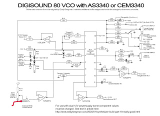
Below here is the new version of the schematic, with all the opamp buffer stages drawn in. All the outputs are buffered and the same with the PWM input. (PWM = Pulse Width Modulation for the squarewave) So a total of 4 buffer stages are used here, all housed in one IC, the TL074. Now, it's not necessary to actually buffer the 3340 outputs because they are already buffered inside the chip itself but we use the TL074 to get all the different output levels that the 3340 produces into line and make them all the same level.
Below here is the new version of the schematic, with all the opamp buffer stages drawn in. All the outputs are buffered and the same with the PWM input. (PWM = Pulse Width Modulation for the squarewave) So a total of 4 buffer stages are used here, all housed in one IC, the TL074. Now, it's not necessary to actually buffer the 3340 outputs because they are already buffered inside the chip itself but we use the TL074 to get all the different output levels that the 3340 produces into line and make them all the same level.
Each output opamp is wired in such a way that it outputs the waveform at 0 to +10 Volt (when using +/-15V powersupply). For the quad opamp chip you can also use a TL084 or an LM324 or any other low noise quad opamp with the same pinout. (There's a link at the bottom of this article to the original text and schematic.) I did not include any de-coupling caps in this schematic but I have included them in the stripboard layout.
Here is a link to the Datasheet of the AS3340: ---CLICK HERE---

The stripboard layout I made from this schematic (further down the article) is verified and the placing of the buffer stages follows the numbering on the schematic drawing. For the Octaves control I used to recommend you use a 100K potmeter with a center detent, but I think after due consideration that it's better overall to use normal linear potmeters. I thought it would be useful to easily re-tune the VCO after you've been using the Octaves control knob and it is, but those potmeters often are not linear. Often they are logarithmic towards the center point. Anyway, decide for yourself what you want but whatever you choose use a normal 100K potmeter for the Frequency Fine control not one with a center detent because you need accuracy around the center settings.


The Bill of Materials: 


Stripboard only:

Cuts and wirebridges:


In the picture below you can see that all ground connections have been made with a bare copper wire, so only one ground wire will actually go to the ground on the stripboard. Do NOT rely on the metal of the faceplate alone to ground the sockets!! This will give you problems. Make sure all sockets are properly grounded to the stripboard like in the picture below.


I did not use the Soft Sync option. I also left out the 1V/Oct output and the extra synchronization or tuner output that I put in my other Kosmo sized VCO's. There's no room for that here and I don't need it. The PWM mixer works remarkably well. You have full control over internal and external Pulse Width Modulation. The hard sync sounds great, especially the 'both' mode (middle input). It took a good 15 minutes to tune but then I had it in tune over 6 octaves at +/-8 cents over the entire range. That is a great result!


Here are the two identical VCOs side by side in my synth. You can see a 'Tuner' and 'Sync Out' output, which I added later on. More on that in the 'Synchronizing' section below:

About the CV-OUT connector:
You can see in the picture that I have CV-OUT jacks on the VCO's. These are simply in parallel over the 1V/Oct. input jack so I can daisy-chain more VCO's to one 1V/Oct. signal so that all VCO's receive the 1V/Oct signal from the Doepfer A-190-3 MIDI to CV converter. This is not included in the stripboard layouts but you can see it in the schematic drawing.
OCTAVE SWITCH:
With VCO number four I changed the Octave potmeter for an octave switch, as an experiment. I used a 10 step rotary switch and I measured out a bunch of 10K resistors so I had 10 with the same resistance upto 10 Ohm accuracy. They were all 9K99. I soldered on the resistors in the way shown in the drawing below:

So you get 5 Octaves up and 4 Octaves down with a 10 step switch. If you want -5/+5 you'll need a 11 step switch, which you can easily find on eBay. This is more than enough though.
Now, this works but it is not the case that when you turn the switch you land on the exact same note as the previous Octave. To try and address that problem I exchanged the 10K resistor connected to -15V for a 10K multiturn potmeter, with a 2K resistor in series with it, going to -15V. Now it's not possible to tune it so it is spot on but I did manage to tune it so that each octave I go up, I can turn the Fine Tune one stripe up on the dial (decal) and I'm in tune. So you switch one Octave higher, you turn Finetune to the next stripe on the dial and you're bang on. And the same but backwards for switching down the octaves. This works well enough for me :) This will really only work well if you also have a hacked Joyo tuner connected to the VCO so you can see what you're doing.
To get this bang on the right note, you would need to experiment with the 3M3 resistor and try to buffer this potmeter and use really accurate resistors. So I wouldn't advise this switch solution, as it is presented here, for any serious project where everything needs to work perfectly. I'm just documenting it here because it is something I personally tried and want to keep a record of.
Here's a picture of the switch in the panel:

The output waves:
And finally a look at the waves this oscillator puts out. All nice clean waves as may be expected from the AS3340 chip but the ringing issue in the downward slope of the squarewave, which I mention in article 2 of this build series, is still there even in this design. Although it is significantly less prominent. This ringing must be common to this chip or something. Anyway, it's not audible so no real problem. I thought the zener diode over the squarewave output resistor might help to eliminate this problem but it has no influence but you can see from the pictures below that there are only a few spikes and only on the lowest notes. The picture below shows the ringing at note C1. Only 3 spikes! They only occur on the downward slope of the squarewave and they have a frequency of 28kHz so well above human hearing capabilities. BTW, I just found out that to get rid of this ringing you can connect a 1M resistor between pins 4 and 5 of the 3340 chip. But this is not implemented in the layout.

At note C3 there's only one spike left and after that it is completely clean. Maybe it adds to the character of the sound though. Who knows ^___^

Squarewave. You can see that the ringing is not even visible once you zoom out of the oscilloscope image:

Here's the ramp wave:

And this is the triangle wave:

Just for fun, here's a Triangle and a Ramp wave after being mixed together and after it's been through the dual Korg MS20 filter. You can see the high frequency resonance, produced by the filter, on parts of the wave form:

You can see that the output voltages are all around the +10 Volt except for the squarewave which is +13.4 Volt. I recently received a batch of 10 Volt Zener Diodes from China and I have soldered one in over the squarewave output and now all signal outputs are at the same 10Vpp level. Perfect! You might have wondered why there is a 2K resistor (R22) in series with the squarewave output. Well, it's there to make the Zener-diode work. Zener-diodes always need a resistor in series with them for them to function as voltage regulators. The zener brings down the voltage from 13.4V to 10V so there's 3.4 Volt that has to be shaven off. That voltage is dropped over the 2K resistor and that's why it's there.


ADDING A SINEWAVE OUTPUT TO THE VCO:


.jpg)
I put in a 47K resistor for R21 which is the pull down resistor for the squarewave output. It originally was a 10K resistor in the Digisound-80 circuit, because the CEM3340 chip was used, and that will work fine too. (Use 10K if you're using a CEM chip) It's stated in the datasheet for the AS3340 that it needs to be 51K but in practice it doesn't matter at all, so I use 47K. For the current limiting resistor (R23) I put in a 1K. This is necessary because we will connect it to negative 15 Volt. It says to use a 910 Ohm in the schematics but I always play it safe and use a 1K resistor. Use a good quality polystyrene or polyester or silver mica type capacitor for C7 (1nF). This is the frequency determining capacitor (a.k.a. timing cap) and must be stable with temperature changes. So do not use a ceramic capacitor for C7. When soldering in a polystyrene capacitor, make sure you don't heat it up too much! These types of capacitors can change their value if they get too hot from soldering and when they cool down the value will stay changed. But don't worry, with normal soldering they will be fine and I never had problems with them myself. Some polystyrene capacitors have a black line on one side. This indicates the leg that is connected to the outer layer of aluminium that makes up the capacitor. This leg should be connected to the lowest voltage potential (usually ground), that way it will act as shielding against hum. If it doesn't have a stripe, just put it in anyway you want. It'll work fine.
This is what a Polystyrene capacitor looks like. You can see that the right side, where the leg enters the capacitor, has a dark band, indicating the right leg is connected to the outer layer of aluminium:

CHANGES FOR RUNNING THIS VCO ON A DUAL 12V POWERSUPPLY:
If you're going to use this VCO with a dual 12 Volt power supply (Eurorack/Kosmo) then use a 680 Ohm resistor for R23. (On the stripboard layout R23 is the 1K resistor going from pin 3 of the AS3340 to the negative 15 Volt rail.) It doesn't matter if you are using the CEM3340 or the AS3340 ICs.
Further down this article, in the 'Tuning' section, I mention that if you experience problems with tuning while running this VCO at 12V, you can make R4 bigger. Use a 270K or even a 300K resistor instead of the 200K. Some people experienced problems because trimpot-A was at its end before the VCO was in tune. Making R4 bigger will prevent that. It's not always necessary to make this change but if you do, you may have to experiment to find a value that works best for you. It seems many people have different experiences with this but it's just a matter of finding the right value.

Temperature Compensation:


(07-June-2020 Revised version. Numbering now follows numbering on schematic.)
Please note there's an extra Triangle to Sinewave converter stripboard you can add to the VCO, to give it a Sinewave output, at the bottom of this article!


Cuts only, component side. Mark the cuts first with a Sharpie on the component side and then stick a pin through the marked holes and mark them again on the copper side. Then cut away the copper at the marked positions with a sharp hand held 6 or 7mm drill bit.
If you're going to use this VCO with a dual 12 Volt power supply (Eurorack/Kosmo) then use a 680 Ohm resistor for R23. (On the stripboard layout R23 is the 1K resistor going from pin 3 of the AS3340 to the negative 15 Volt rail.) It doesn't matter if you are using the CEM3340 or the AS3340 ICs.
Further down this article, in the 'Tuning' section, I mention that if you experience problems with tuning while running this VCO at 12V, you can make R4 bigger. Use a 270K or even a 300K resistor instead of the 200K. Some people experienced problems because trimpot-A was at its end before the VCO was in tune. Making R4 bigger will prevent that. It's not always necessary to make this change but if you do, you may have to experiment to find a value that works best for you. It seems many people have different experiences with this but it's just a matter of finding the right value.
When running this on dual 12V you might also need to lower the value of C7 from 1nF to as low as 0.5nF (or 500pF). Otherwise you might only get very low frequencies out of this VCO. This is not in the Datasheet but it has been established by feedback from many readers who built this VCO for Eurorack. Again, this change is also not always necessary but I leave it up to you. Many people commented that they needed to do this change to get it working right on 12V. Halving the value might be a bit too harsh though. In my own VCO's I changed the value to 820pF and that was more than enough. Make sure you don't use ceramic caps for C7. They are too temperature sensitive and make your VCO go constantly out of tune.
I also had feedback that mentioned changing R7 from 300K to 150K. This is the resistor in series with the wiper of the Octaves control potmeter. This will increase the range of the Octaves potmeter. Again, I'll leave it up to you whether you need this change or not. I tried it and it made the Octaves range far too sensitive. I'd go from C2 to C0 in about 20° of turn. I do not recommend this change. It's not necessary even when you run it on +/-12V.
Next thing to do is to change R18, the resistor connected to the PWM potmeter to 18K or 20K or 21K (which ever value you have to hand) to make full use of the throw of the pulse width modulation potmeter. You could even put in a 33K trimpot and then set it so that the voltage over the PWM potmeter is exactly +10V but it's not necessary to go that far. A resistor is fine as long as the value is around the 20K, plus or minus 2K.
Finally, some useful feedback I got via the LookMumNoComputer forum is to change R11 from 1M5 to 1M2. This should really help with tuning especially if changing R4 doesn't improve the tuning situation much. With all these changes you should be able to get it working fine on +/-12V.
So to sum up the changes you need to make for +/-12V operation:
- Change R23 to 680 Ohm.
- Change the Timing Capacitor C7 from 1nF to 820pF. If you still have trouble reaching high octaves or with tuning then you can use a 680pF or 500pF. Experiment and see what works for you. In my own Eurorack versions I used 820pF capacitors.
- Change resistor R4 (200K in series with Trimmer A) for a 270K or 300K resistor if you have problems with tuning (again, only if necessary. I just put in a 220K and it worked fine on 12V)
- Change R18 to 18K, 20K or 21K. This is to get the full Pulse Width range on dual 12V. This resistor is soldered straight to pin 3 or the Pulse Width potmeter.
- Change R11 from 1M5 to 1M2. This will help with tuning and if you're having problems to get the VCO to track right over the octaves. This is a change I strongly recommend!
- One extra thing: solder a 1M resistor between pins 4 and 5 of the AS3340. This will get rid of any high frequency ringing in the squarewave (see scope picture further down the article). This change is not made yet in the layouts below and not necessary for the VCO to work but highly recommended. There's place enough to put one in.
HOW TO MAKE THIS VCO A BI-POLAR VCO (+/-5V INSTEAD OF 0-10V).
To change this VCO into a bi-polar one, replace the 1K output resistors for the Sawtooth- and Triangle waves with 470nF capacitors. These are the 1K resistors connected to pin 14 of the TL074 and to pin 1 (in some layouts via a wirebridge).
I have done tests on this and it works fine even for the squarewave output but with quickly changing pulse widths it does need time to settle around the zero volt line. So I took a different approach for the squarewave. I adapted the squarewave buffer opamp with an offset trimpot so you can set the squarewave to +/-5V to get a bi-polar output without the need for a capacitor. This makes the squarewave very stable even with fast changing pulse widths.
Here's a look at how I changed the Squarewave output opamp in such a way that we can introduce a negative 5V offset voltage to make the output +/-5Vpp.

It's too much work for me to adapt all the layouts to include this change but I did one layout. the Eurorack version with all the bells and whistles, the fourth one down.
One final note on the capacitor method: The common argument against using capacitors to get rid of offset voltages is that it works as a highpass filter in combination with the input impedance of the next module the VCO signal will be connected to. This is true but most modules have inputs that go through an opamp and they have infinitely high input impedance so most of the time that problem doesn't really occur. With 470nF and an input impedance of 10K (which is very low) the cutoff freq would be 33Hz. At 1M Ohm it's already 0.3Hz so no problem at all even for very low frequency signals. That's why I chose the specific value of 470nF. You can go up to (non polarized) 1µF caps if want to be extra sure. Btw, the VCO can NOT work as an LFO with these changes. It works from about 10Hz upwards.
Did you know that the Behringer 112 dual VCO for Eurorack is a uni-polar VCO? The squarewave and Rampwave are 0V to +10V. Only the Traingle wave is bi-polar. So it doesn't seem to matter much most of the times.
Should you want to revert back to the original state with 0 to +10V signals, all you would have to do is replace the two 470nF caps with 1K resistors and adjust the offset of the squarewave. So it's a very non-destructive method.
Further hints and tips:
The potmeter for High Frequency Tracking or Linearity can be a normal trimpot, not a multi-turn one. The influence it has is minimal. In fact I measured only a 1Hz change in high octaves.
But you must use multi-turn trimpots for A and B on the layout, otherwise tuning will become very difficult. All resistors I use are metal film resistors with 1% tolerance. In fact, I used cheap 1% resistors from China and they are not 1% but more like 3% but this is still good enough. But the 100K CV input resistors should all be measured and matched so they all have the same resistance value. This makes it easier when you connect different CV sources to those inputs, they will be in tune straight away. I was surprised that the two 100K potmeters I used in the panel for Octaves and for Fine Tune give exactly the range that is stated in the original description although the Octaves control is not linear, at least mine wasn't but maybe that is due to the potmeters with center detent I used. Octaves is plus and minus 5 octaves and Fine is plus and minus half an octave. I'm not used to things actually working out as originally described in DIY projects. It's usually either a bit off or way off but the Digisound 80 designs are really good and spot on.
If I can give you one important tip, and this goes for all the projects on this website: Measure every component before you solder it in place. This can save you an enormous amount of work in troubleshooting
Before I made the bi-polar version of this VCO, I made separate quad offset boards that you could add on as a means of changing 0-10V into +/-5V. They have become more or less obsolete for this project but I'm leaving the project up on the website. It might be useful to someone.
TIP: SET YOUR OSCILLOSCOPE TO DC WHEN MEASURING OUTPUT SIGNALS!! Otherwise you'll get wrong readings and it won't measure DC offset voltage.
About Pulse Width Modulation:
Pulse Width Modulation is now also spot on. Before the 18th of October 2020 I had the PWM connected as is shown in the original schematics in the PDF file linked below (in series with the wiper of the PWM potmeter) but that didn't work perfectly. There was a significant amount of throw left on the potmeter when you reached the 100% mark. However, I got a suggestion in the comments below to move R18 from the wiper of the PWM potmeter to pin 1, the +15V connection to the potmeter, and that did the trick.
Pulse Width Modulation is now also spot on. Before the 18th of October 2020 I had the PWM connected as is shown in the original schematics in the PDF file linked below (in series with the wiper of the PWM potmeter) but that didn't work perfectly. There was a significant amount of throw left on the potmeter when you reached the 100% mark. However, I got a suggestion in the comments below to move R18 from the wiper of the PWM potmeter to pin 1, the +15V connection to the potmeter, and that did the trick.
I should have realized this myself it's so obvious. The 47K resistor R18 forms a voltage devider with the 100K potmeter that takes off 5V from the +15V supply and leaves the potmeter with +10V on pin 1. This is then halved by the voltage devider made up of R19 and R20 (both 47K) to feed the chip with 0 to +5V, which is exactly what it needs for the correct pulse width modulation.
This Pulse Width problem was really buggin' me because it was the only thing that was not working right in this design but now that is solved too.
The results I get are as follows: With the PWM potmeter fully counter clockwise I get 0% pulse width, meaning that there is no signal, just a flat line. Then as I turn it clockwise the pulse appears and goes through the percentages to stop at 99% pulse width when the potmeter is turned fully clockwise. So fully clockwise there's a very thin pulse left over. This is absolutely perfect. Of course your results can differ a tiny bit because of resistor tolerances but I got the same results with all 4 of my VCO's.
So if you are using this VCO with a Eurorack powersupply of +/-12V you need resistor R18 to be near to 20K. (21K or 18K will work fine I think. The schematic and layouts have all been updated with the new R18 position.)
For external Pulse Width Modulation you need a signal that goes from 0 to +10V on the PWM input jack. This can be a problem if you use this VCO in a Eurorack setting where the signals are usually -5/+5V. Just so you know. But there are LFO designs on my website that will give you the 0V to +10V output option you need. You can also use a module like the Dual Voltage Processor to give a +5V DC-Offset voltage to the control voltage and then use it for Pulse Width Modulation.
NB: If you have built this VCO and all the waves work except for the squarewave then check the voltage on pin 5 and see if it is between 0 and +5V. If not, the output will be a flat line because the Pulse Width will be set below 0% or above 100%.
SOLDER A 1M RESISTOR BETWEEN PINS 4 AND 5 OF THE AS3340. THIS WILL PROVIDE SOME HYSTERISIS TO THE SQUAREWAVE AND PREVENT RINGING.
Temperature Compensation:
Don't place this VCO directly over the power supply in your modular set-up. If it gets influenced by the heat from the voltage regulators too much it can de-tune a bit but I think this is true of almost all VCO's. The AS3340 has internal temperature compensation but this only really works for changes in room temperature. If you put it over a heat source like a power supply it will most definitely de-tune. Of course other components around the chip will also warm up and add to the de-tuning of the VCO when influenced by the heat from the powersupply heatsink.
1. KOSMO SIZED LAYOUT:
1. KOSMO SIZED LAYOUT:
Below here is the layout. I didn't put in the input jacks for the sync inputs or the output jacks for the wave forms and CV-OUT. It's already spaghetti junction and that would make it even worse. I assume you know how to hook up jack sockets. All potmeters are frontal view with shaft facing you. I have recently added 100nF decoupling capacitors directly between the IC's and 22µF electrolytic capacitors on the power rails, because this came up on Facebook. These are not included in the schematic drawing but they are in the original schematic in the PDF linked below. (You can use any value for the electrolytic caps between 10µF and a 100µF as long as they are rated for 25V or over.) There's an extra CV input marked on the layout. This is just incase you want to permanently connect something, like a sequencer, to the VCO and don't want to sacrifice an existing CV input for that. (If you don't need it, there's no need to include it.)
Again I want to repeat what I said earlier: measure every components value before you solder it in. I always do this myself too because resistors and especially capacitors can be way out of spec sometimes and it is always best to be sure, especially when using cheap Chinese components. (I always use cheap resistors and they work just fine.)
I added and extra Hard Sync input to this layout recently. You can install a 3 way rotary switch for the Hard Sync and have some options this way. You can also leave it out, it's up to you. (The middle hard sync input comes from the Digisound 80 VCO Deluxe schematic.)
Here's the wiring diagram. This version runs on +/-15V:

And here's a close-up of the stripboard. Don't forget to cut the copper strip underneath the 1M resistor above trimpot A. (Position A-31) The cut is difficult to see on the layout but it's there of course, otherwise the resistor wouldn't work. Also don't forget the jumpwire from that resistor to the wiper of trimpot C! (Position B-16 or 17). I made an extra layout with just the cuts and wirebridges, below.
Beware that some stripboards are sold with 56 instead of 55 holes horizontally. This layout is 55 holes wide.
Stripboard only view:

Below an overview of the cuts and wirebridges seen from COMPONENT SIDE! As always, mark the cuts on the component side with a waterproof Sharpie and then stick a pin through the marked holes and mark them again on the copper side. Then you can make the cuts with a sharp hand held 6 or 7mm drill bit. Then lightly rub the copper strips with a fine grain sandpaper.
Cuts and wirebridges:

Bill of Materials.

(07-June-2020 Revised version. Numbering now follows numbering on schematic.)
Please note there's an extra Triangle to Sinewave converter stripboard you can add to the VCO, to give it a Sinewave output, at the bottom of this article!
2. EURORACK SIZED VERSION.
This version is the same as the above only the components are packed tighter together so the stripboard is only 40 holes wide which will make it fit behind a 14hp Eurorack panel.
A few resistor changes for use with a dual 12V powersupply have been made in this layout! The timing capacitor C7 is the same 1nF as in the 15V version but in my build (further down the article) I used a 820pF cap. Make sure it's a good quality capacitor not a ceramic one. R11 was changed from 1M5 to 1M2, R23 was changed from 910 (or 1K) to 680Ω. All the other changes I mention at the top of the article I left out to see if they were really necessary. In this case they weren't.
I also made a Eurorack layout which includes an alternative version for the Pulse Width Modulation input. You can input an external pulse width Control Voltage and still use the internal PWM potmeter too. Both CV's are summed in an opamp before being input in the AS3340 chip. That's version 4 further down.
Wiring diagram. This version runs on +/-12V.:

Stripboard only:

And the cuts and wirebridges.


3. KOSMO SIZE with ALTERNATIVE PWM INPUT.
I've had a request for an alternative solution for the pulsewidth modulation inputs. This person wanted to be able to have the pulse width connected to an LFO and still be able to control the pulse width on the panel as well. So I designed a little CV-mixer stage as an alternative for the standard PWM inputs. It requires an extra opamp but there is just enough room for that on the stripboard:

Here's the total view layout for this alternative version:

Stripboard only. The version as shown here runs on +/-15V. If you want to run it on +/-12V you need to make the same changes as the previous ones. The timing capacitor C7 goes from 1nF to 820pF. Make sure it's a good quality capacitor not a ceramic one. R11 changes from 1M5 to 1M2, R23 changes from 1K (or 910Ω) to 680Ω.
These changes are not implemented in this layout, only in the eurorack layouts.

I tested this PWM setup in the Eurorack version below and it works perfectly. Make sure you make the extra cuts and wirebridges etc. I made an extra layout to help you with this:

Bill of materials for the above version with Pulse Width Modulation CV-mixer:

Schematic for this version:

4. EURORACK SIZED BI-POLAR VERSION with ALTERNATIVE PWM INPUT MIXER.
I decided I had to also make a Eurorack version that included the above mentioned alternative pulse width modulation input mixer and I decided to make this a Bi-Polar version. So below is a layout that fits behind a 14hp Eurorack panel and includes the PWM mix input and the squarewave offset function so you can trim it to be bi-polar and it has 470nF caps on the triangle and sawtooth outputs.
I realized that I could actually do without one opamp in the PWM mixer section and that saved just enough space to make this layout size possible. You will notice that pins 1,2 and 3 of the TL072 are not used and that opamp is tied to ground.
A few resistor changes for use with a dual 12V powersupply have been made in this layout! The timing capacitor has been changed to a 820pF cap. R11 was changed from 1M5 to 1M2, R23 was changed from 1K (or 910Ω) to 680Ω. All the other changes I mention at the top of the article I left out to see if they were really necessary. In this case they weren't. I also changed R4 to 220K instead of 200K to ease tuning. You can also use a 270K.
(Layout is verified.)
Wiring diagram:


Cuts seen from COMPONENT SIDE.
Mark the cuts first with a Sharpie on the component side and then stick a pin through the marked holes and mark them again on the copper side. Then cut away the copper at the marked positions with a sharp hand held 6 or 7mm drill bit.

And finally the Bill of Materials for this version:

SCHEMATIC:
The schematic for the above version is the same as the one in section 3 only I used one less opamp in the PWM mixer.
The schematic presented here is for the bi-polar Eurorack PCB version with the PWM Mixer, made in KiCad by yours truly. With the component values shown here, this VCO runs excellently on +/-12V. It was very easy to tune too.
(This is an updated schematic as of the 13th of November 2025. The previous version had the wiper of the grounding switch to the potmeter instead of the circuitboard which can cause short circuits.)

I added an offset trimmer so the squarewave can be trimmed to +/-5V instead of 0-10V. I used 470nF capacitors in series with the Triangle- and Sawtooth wave outputs to make them bi-polar too. Please note the layouts in this section are not the bi-polar version. I might make one soon though.
I also added a 1M resistor between pins 4 and 5 of the 3340 chip. This will prevent any weird ringing on the squarewave as shown in the scope screenshots below. This resistor is not in the layouts but can be easily added.
The bi-polar version can not be used as an LFO. It only works from about 10Hz upwards.
These bi-polar changes are only made in the PCB versions, for sale in the webshop, not the stripboard layout.
Before I had the PCB's I started building this version for myself on stripboard because I could use an extra VCO for my Eurorack system and of course I want to test these new layouts so I can verify them myself. I wired it all up and I can tell you that this layout is verified. It works like a charm. :)
Mind you, the stripboard version is not bi-polar. It's 0-10V. But you can easily adapt it.

Faceplate all stocked ready for wiring up. It is 14hp wide (7cm) and the depth, when it was all finished, came to 4CM:


The finished product.

I used a 820pF polystyrene capacitor for C7 to be on the safe side when it came to tuning and this worked out really well.
At first I just labelled the faceplate but I later made a new one this time using waterslide decals for the first time ever for me. It looks really good in the picture but there are some creases and it's a bit rough. So I still have some learning to do on this subject but the first result is encouraging.

THIS CONCLUDES THE DIFFERENT VERSIONS AND WE NOW CONTINUE DISCUSSING THE VERSION I BUILT FOR MY OWN MODULAR SYNTH.
(The normal Kosmo sized VCO).
Below is a look at the finished stripboard. I soldered on a little copper eye to make mounting the stripboard on the particular panel I made easier, but there's room enough left on the stripboard to drill a few holes to mount it however you like. Make sure the copper traces are cut so no contact is made with the screw and nut etc. In this picture you can also see the annoying little circle at the bottom of the AS3340 chip. Do NOT mistake this for the pin-1 indicator, and put the chip in the wrong way as I once did!! I had the chip mounted in the socket the wrong way around and had it switched on for about 20 seconds. It got so hot that I could smell it, that's what allerted me, and I switched it off immediately thinking the chip would be waisted but no, it survived! (They call that 'burning in the chip', LOL. DON'T TRY IT!)

Here are the two identical VCOs side by side in my synth. You can see a 'Tuner' and 'Sync Out' output, which I added later on. More on that in the 'Synchronizing' section below:

About the CV-OUT connector:
You can see in the picture that I have CV-OUT jacks on the VCO's. These are simply in parallel over the 1V/Oct. input jack so I can daisy-chain more VCO's to one 1V/Oct. signal so that all VCO's receive the 1V/Oct signal from the Doepfer A-190-3 MIDI to CV converter. This is not included in the stripboard layouts but you can see it in the schematic drawing.
If you use the Dual Buffered Multiple described on this website, then you don't have to include this CV OUT and you can spread the 1V/Oct. signal over all VCO's with the Multiple. But I do advise to include it. If you daisy-chain your oscillators like this you keep the Buffered Multiple free for other functions and you can daisy-chain upto 8 oscillators of this design before you'll get a slight drop in voltage in the 1V/Octave signal.
TURNING THE 0 TO +10Volt SIGNALS INTO -5V to +5Vpp SIGNALS:
TURNING THE 0 TO +10Volt SIGNALS INTO -5V to +5Vpp SIGNALS:
Before I used the capacitor and offset method to make the VCO bi-polar, I made a little expansion board with 4 inputs and 4 outputs that gives you the option of giving a -5V offset voltage to the waveforms this VCO outputs and so turn them into bi-polar signals. This will make sure you can use this VCO with all the other projects on this website without the problem that the signals are 0-10Vpp. Most modules require signals that are -5/+5V peak-to-peak. This expansion board will provide that for you. You will have to find a way to implement this stripboard in your module design but if you're handy you will find a way. Anyway I leave that up to you. Here is the link to the expansion board project, Synthesizer Extra's No.4:
Synchronizing multiple VCO's:
I recently added two more outputs. One is parallel over the squarewave output socket and is used to connect the VCO to the negative Hard Sync of one of the other VCO's, so I can keep the Squarewave output free for normal use. The other output is in parallel over the triangle wave output and is used to connect the hacked Joyo tuner to the VCO, also to keep the Triangle output free for normal use. These outputs are not on any of the pictures or on any of the layouts but you can easily add them if you feel you need them. I find them very useful. If you want to synchronize two VCO's then just take a square- or sawtooth-wave out from the main VCO into the Negative Hard Sync input of the second VCO.
The main function of the sync options on this VCO is actually not to have them track together but to create more interesting sounds. If you input a VCO signal into an other VCO's Hard or Soft Sync input you can get some really cool results if you change the frequency of the secondary VCO with the Octaves control potmeter. It will produce higher tones but the waveforms will be cut to the frequency of the synced VCO giving you all sorts of overtones and harmonic frequencies. If you never tried this I strongly recommend experimenting with this. (Also see the article about the Thomas Henry VCO-555 about synchronization). You will get that famous FM synth sound that can be really phat and rich in harmonics.
The difference between Hard Sync and Soft Sync is that with hard sync de oscillator always resets the waveform when it receives a sync pulse. With soft sync it only resets the waveform if the slope of the incoming signal is within a percentage distance to the slope of the original signal. So it will ignore the sync signal unless the two oscillators (master and slave) are tuned close to some octave interval. With hard sync it doesn't matter, it will always force a reset and that's why it sounds harder and harsher. Negative, Both or Positive hard sync just determins if the waveform is reset on the negative going slope, both slopes or the positive going slope of the incoming signal. Funnily enough I never had much success with Positive Hardsync with this VCO design for some reason. Maybe I'm doing something wrong. On the Eurorack version it was the negative Hard Sync that wouldn't work LOL. Oh well.
MIDI to CV converter, the Doepfer A-190-3V:
In order for the VCO to produce actual notes we need to feed it with a control voltage that follows the 1Volt per Octave standard. For that we need a converter that turns the MIDI signals from a keyboard into a 1V/Oct CV signal. You can of course use a keyboard that outputs CV signals like the Beatstep Pro or Keystep from Arturia but I assume you want to add a real MIDI converter to your setup.
Now, you can build a MIDI to CV converter yourself but I didn't trust myself to build one and I wanted the interface between the keyboard and the synthesizer to be absolutely fool-proof and reliable. So I bought my first Eurorack module: a DOEPFER A-190-3 MIDI to USB and CV converter and it was certainly worth the €130 I paid for it. You can connect any keyboard, that has a 5 pin MIDI output, to it and it will output a 1V/Octave Control Voltage. It adds a Portamento (or Glide) function to the synth and besides the normal CV out it has 3 extra outputs for the modulation and pitch-bend wheels on the keyboard that you can connect to CV-2 for instance to get pitch-bend. It also has a Velocity output and a 'Learn' option on CV-4. It will assign CV4 to any mod wheel or knob that you touch on the keyboard. And it also has a USB input so I can connect the synth to my computer. Naturally it also produces a Gate signal for the Envelope Generator. The voltage of all the outputs can be set with jumpers on the circuit-board. I got the A-190-3V which is the Vintage edition which means the panel is black with white lettering to stay in keeping with the other panels in my synth. It's only 5 more euro's than the normal silver edition. I just made a 20cm high panel and cut a Eurorack sized hole in it. I first made it from cardboard so I could easily adjust the size of the hole and when it was ready I transferred it to an Aluminium panel and mounted the Doepfer in there. Then I made a special adapter cable to go from the Eurorack power system to the one I invented for my own synth. (See powersupply article).
I now also have the original Mutant Brain from HexInverter which can be re-programmed via MIDI to be polyphonic (which I have done). These original versions are no longer available and the Mutant Brain is now made by Erica Synths but that version can not be re-programmed.
OCTAVE SWITCH:
With VCO number four I changed the Octave potmeter for an octave switch, as an experiment. I used a 10 step rotary switch and I measured out a bunch of 10K resistors so I had 10 with the same resistance upto 10 Ohm accuracy. They were all 9K99. I soldered on the resistors in the way shown in the drawing below:

So you get 5 Octaves up and 4 Octaves down with a 10 step switch. If you want -5/+5 you'll need a 11 step switch, which you can easily find on eBay. This is more than enough though.
Now, this works but it is not the case that when you turn the switch you land on the exact same note as the previous Octave. To try and address that problem I exchanged the 10K resistor connected to -15V for a 10K multiturn potmeter, with a 2K resistor in series with it, going to -15V. Now it's not possible to tune it so it is spot on but I did manage to tune it so that each octave I go up, I can turn the Fine Tune one stripe up on the dial (decal) and I'm in tune. So you switch one Octave higher, you turn Finetune to the next stripe on the dial and you're bang on. And the same but backwards for switching down the octaves. This works well enough for me :) This will really only work well if you also have a hacked Joyo tuner connected to the VCO so you can see what you're doing.
To get this bang on the right note, you would need to experiment with the 3M3 resistor and try to buffer this potmeter and use really accurate resistors. So I wouldn't advise this switch solution, as it is presented here, for any serious project where everything needs to work perfectly. I'm just documenting it here because it is something I personally tried and want to keep a record of.
Here's a picture of the switch in the panel:

The output waves:
And finally a look at the waves this oscillator puts out. All nice clean waves as may be expected from the AS3340 chip but the ringing issue in the downward slope of the squarewave, which I mention in article 2 of this build series, is still there even in this design. Although it is significantly less prominent. This ringing must be common to this chip or something. Anyway, it's not audible so no real problem. I thought the zener diode over the squarewave output resistor might help to eliminate this problem but it has no influence but you can see from the pictures below that there are only a few spikes and only on the lowest notes. The picture below shows the ringing at note C1. Only 3 spikes! They only occur on the downward slope of the squarewave and they have a frequency of 28kHz so well above human hearing capabilities. BTW, I just found out that to get rid of this ringing you can connect a 1M resistor between pins 4 and 5 of the 3340 chip. But this is not implemented in the layout.

At note C3 there's only one spike left and after that it is completely clean. Maybe it adds to the character of the sound though. Who knows ^___^

Squarewave. You can see that the ringing is not even visible once you zoom out of the oscilloscope image:

Here's the ramp wave:

And this is the triangle wave:

Just for fun, here's a Triangle and a Ramp wave after being mixed together and after it's been through the dual Korg MS20 filter. You can see the high frequency resonance, produced by the filter, on parts of the wave form:

You can see that the output voltages are all around the +10 Volt except for the squarewave which is +13.4 Volt. I recently received a batch of 10 Volt Zener Diodes from China and I have soldered one in over the squarewave output and now all signal outputs are at the same 10Vpp level. Perfect! You might have wondered why there is a 2K resistor (R22) in series with the squarewave output. Well, it's there to make the Zener-diode work. Zener-diodes always need a resistor in series with them for them to function as voltage regulators. The zener brings down the voltage from 13.4V to 10V so there's 3.4 Volt that has to be shaven off. That voltage is dropped over the 2K resistor and that's why it's there.
I made a little demo video showing the main features of this VCO. Sorry it's not very good, speech is not loud enough. Don't be fooled by the scope image, the signal really is 0 to +10Vpp but the scope measures the VCA output and that is -5/+5V. The VCA is also the cause for the slight rounding in the saw- and triangle waves. You can not hear that in the sound though. The VCA works fine. Btw, this video was made before I added the Sinewave option so that is not demonstrated here.
One other thing: Please keep in mind that this project and this demo video were made in the early stages of my synthesizer building career (around early 2020) and thus I was not yet fully aware of everything you could do with a VCO in terms of using Synchronization and FM Modulation so therefor this demo is a bit basic.
Here's another video not by me demonstrating this VCO:
TUNING THE VCO:
This VCO has 3 trimpots for tuning but we're only going to use 2 because the High Frequency Tracking or Linearity potmeter is not really effective for the lower octaves. So we leave that in the middle position. I have developed a tuning procedure of my own that is very simple and will get this VCO in tune over many octaves in less than 15 minutes.
If you don't have a useful tuner for calibration purposes but you do have a smart-phone then I recommend you download the 'Universal Tuner' app by Dmitry Pogrebnyak. This app can tune anything. Set it to the Chromatic Scale for tuning VCO's. It's available in the Google Play store for free. I personally use the Airyware Tuner a lot. This is an app on Android (and iPhone I think) and it is even used in the Rhodes factory to tune their electric pianos. Get the paid version, it's cheap and feature rich. I use it to tune my Bass guitar too. Of course any tuning app that displays frequency and notes will do. There's plenty to choose from. Anyway........... where was I?
If you don't have a useful tuner for calibration purposes but you do have a smart-phone then I recommend you download the 'Universal Tuner' app by Dmitry Pogrebnyak. This app can tune anything. Set it to the Chromatic Scale for tuning VCO's. It's available in the Google Play store for free. I personally use the Airyware Tuner a lot. This is an app on Android (and iPhone I think) and it is even used in the Rhodes factory to tune their electric pianos. Get the paid version, it's cheap and feature rich. I use it to tune my Bass guitar too. Of course any tuning app that displays frequency and notes will do. There's plenty to choose from. Anyway........... where was I?
Before we start tuning, turn the Coarse Tune or Octaves potmeter off with the switch on the panel and set the Fine-Tune potmeter in the middle position. In the original text the wire connected to the wiper of the Fine Tune potmeter is de-soldered, but I recommend just leaving it in the middle position. Now turn the two trimpots all the way to one side until you hear it clicking. That means it's at the end. It doesn't matter which way you turn. Take a little screwdriver and turn trimpot A up about 3 quarters of the way (that's 22 out of 30 turns). Now go to trimpot B and turn that up about 1 quarter of the way (That's about 7 turns. It's not necessary to be accurate with this and it also doesn't matter which way you turn them. It's just for setting a start position.)
If you want to be extra precise then let the VCO warm up for 15 minutes after turning it on so it can reach its normal operating temperature, before starting to tune it.
- Launch the Universal Tuner app. on your smartphone or use the tuner of your preference.
- Open up the 'Gain' potmeter on your VCA so you get continuous sound.
- Now press key C5 on your keyboard and turn Trimpot A until note C5 is in tune on your tuner.
- Now press key C2 on your keyboard and turn Trimpot B until C2 is in tune.
- C5 will now be out of tune again so press key C5 and retune it with Trimpot A.
- Now C2 will be out of tune again so press C2 and retune it with Trimpot B.
- Repeat these steps over and over until the VCO is in tune.
- You'll notice that you will need to turn the potmeters less and less to reach the C notes. After a few cycles of tuning they will be spot on their respective C notes.
- If you find that you need to turn the trimmers more and more to reach the C notes then switch potmeters and use A for C2 and B for C5
TIP: If you are tuning more than one VCO at once, make sure they are all switched on and all other modules in your modular synth are connected too otherwise the slight voltagedrop you get when you switch them all on can de-tune your VCO(s). Have them connected to the same powersupply that you intend to use for your modular system when you are tuning the VCO(s).
We tune with the Octaves control switched off to prevent variations in resistance from de-tuning our VCO. Having the wiper of the potmeter exactly in the middle results in 0V on the 1V/Oct. input so that would be the same as having the wiper disconnected by the switch, but not all potmeters are perfect and that's why we use the switch. Also because a little movement of this potmeter has a huge influence on the frequency. This is less important with the Frequency Fine control although you must make sure not to touch the fine control during tuning and make sure it stays in the 12 o'clock position during tuning.
Be precise with the final tuning. Check the exact frequencies of the C notes. The app I mentioned will display the note graphically and it shows the frequency. You can get it in tune to at least 1/10th of a Hertz although in my experience you don't have to go more than one figure behind the comma.
Here's a PDF about tuning 3340 VCO's that maybe of help to some of you if you have trouble tuning this VCO: -- CLICK HERE --
Extra info for tuning on +/-12 Volt and using the V3340 chip:
As mentioned earlier, if you're running this VCO on +/-12V and you have trouble tuning it, change R4 from 200K to 220K or 270K or even 300K.
I've also had a comment on Facebook about the V3340 chip not holding tracking when used in this circuit. I have no further details on that, but just so you know. It's recommended you use either the AS3340 or the CEM3340 chip.
It will usually be the case, when we start tuning, that the notes are too far apart rather than too close together and if you repeat the steps above and keep switching between C2 and C5 and using trimmer A for the high note and B for the low note, you will notice, as mentioned before, that the notes get closer together and you'll have to turn the trimpots less and less to hit the right note. Eventually you will be spot on and the VCO will be in tune over at least 4 octaves. Be careful that you don't overshoot but you'll notice that soon enough if you have to turn the trimpots more and more to hit the right C note. In that case switch trimpots and use trimpot A for the low note and B for the high note.
You can of course use even higher octaves and other notes, like tune it between A2 and A7 for instance. I leave that up to you. I don't use C1 for tuning because it is so low my phone with the app has trouble tuning into it.
You'll get the hang of this tuning proces soon enough. It's really simple. It took me just 15 minutes after turning the VCO on to have it perfectly in tune, and when I say perfectly I mean perfectly! I was really chuffed about this ^____^
Here is a very interesting article that one of my readers sent to me. It deals with a tuning process for 12 Volt, using four trimmers which only need to be adjusted once, instead of going between two trimmers for ten or more times. I have not tested this methode but it's a very interesting approach so here's the link to the article:
https://cabintechglobal.com/tune3340
Here's a little overview of features and technical data about this VCO:
Frequency range: 0.1Hz - 50kHz
Most accurate freq range: 5Hz - 10kHz
Waveform amplitude: 0V to +10Vpp
Octave adjust control range: +/- 5 Octaves
Frequency Fine control range: +/- 0.5 Octaves
Positive- and Negative Hard Sync and Both.
Soft Sync
Linear Freq. Modulation input with level control.
Frequency range: 0.1Hz - 50kHz
Most accurate freq range: 5Hz - 10kHz
Waveform amplitude: 0V to +10Vpp
Octave adjust control range: +/- 5 Octaves
Frequency Fine control range: +/- 0.5 Octaves
Positive- and Negative Hard Sync and Both.
Soft Sync
Linear Freq. Modulation input with level control.
Optional PWM input mixer that allows you to use an external Pulse Width Modulation Control Voltage and sum that to the internal Pulse Width control so you can have an external PWM CV signal coming in and still be able to use the internal PWM control.
The other (normal) CV inputs are in fact Exponential Freq. Modulation inputs.
CV-2 input with level control. (This is an Exp. Freq. Mod. input.)
Pulse Width Modulation both internally controlled and externally controllable.
Extra CV inputs can easily be added by using 100K resistors connected to pin 15 of the VCO chip. Measure the resistance of the 100K CV input resistors and make sure they are all the same, that way anything you connect to the inputs will be in tune right away.
All outputs are protected and can be short-circuited continuously without damage to any components.
Synchronization and FM input:
The positive Hard Sync synchronizes on the rising edge of a squarewave and negative H.S. on the falling edge. I'm getting excellent results with the Negative Hard Sync and Soft Sync. They all work fine and FM also gives great results. I personally use the negative Hard Sync input for syncing up two or more VCO's. I input a square- or ramp-wave from an other VCO into Neg H.S. and then they both react to pitch changes of the main VCO. The FM input is also very cool to use. I can't describe how it sounds but if you build two of these and input one into the other and you turn the Octaves control back half an octave on the oscillator connected to the inputs, you're gonna get some great results. You can also input a Control Voltage from an LFO to get Vibrato or Tremelo effects. I demo this in the video.
Like I mentioned before, the normal CV inputs are equivalent to Exponential FM inputs. Try connecting the output of an other VCO to a CV input and change the octave of the input VCO upwards. Sounds pretty cool!
Finally and by request, here's a list of individual notes and their corresponding voltages, should you want to tune the VCO without a keyboard, using an accurate voltmeter. Ignore the 'Expo Output' column. It is not relevant to this VCO:


Below are some picture showing how far I've come since building my first VCO in 2019.
Finally and by request, here's a list of individual notes and their corresponding voltages, should you want to tune the VCO without a keyboard, using an accurate voltmeter. Ignore the 'Expo Output' column. It is not relevant to this VCO:

Here's a picture of VCO's one, two and three. The third one is installed at the top in the second case of the Bergman-Berlin synthesizer. I installed a Sinewave output too in VCO-3, but that was after this picture was taken. :)

(Nov. 2025) This is a Digisound-80 3340-VCO completely designed by me in KiCad 9.0. (Also see KiCad tutorial part 2) It consists of two PCB's and a faceplate. The PCB's have been made as one project with a V-groove through the middle so you can break them appart. They connect together with pinheaders.
This VCO is the best VCO I ever built when it comes to performance and tuning. I had it tuned over 6 octaves with a maximum of +2 cents deviation over 5 octaves and -3 on octave 6. It includes a slightly updated version of the triangle to sinewave converter (see below) too so it has the full 4 waveform outputs (bi-polar), all the sync options and all the FM options. So fully featured, and this project was sponsored by PCBWay so the PCB's came free ^____^


I added the Sinewave option to the VCO waveforms by adding an extra bit of stripboard with a Triangle- to Sinewave converter, the design of which I took from the schematic of the Thomas Henry VCO Deluxe which you can find in the 'Files' section of the 'Eddy Bergman Facebook Group'. It's a very simple design so only needs a small piece of stripboard. I think you can easily figure out yourself the best way to add it to your specific VCO panel. I did not use the original Digisound 80 sinewave part of the VCO because it uses a CA3080 chip and there are a lot of fakes of that chip being sold. Anyway I tested that design and could not get it to work.
The Triangle- to Sinewave converter needs a Triangle input wave of +/-5Vpp.
If you only have a 0-+10V Triangle wave available use the 1µF cap on the input to filter out the DC offset.
I changed the design a bit to work well on +/-12V.
I altered the feedback resistor (Rf on the layout) from 10K to 15K to get the amplitude correct with the other waveforms of the VCO. I did the same with the 10K from pin 3 to ground, that's a 15K too now. This brings the amplitude up nicely. If it's still too low for your taste than use 18K's.
You should make sure the other two 10K's are matched and the transistors should also be matched. (Match them on hfe, that's good enough). Put a 1K trimmer between the 10K's at the top with the wiper connected to +12V so you can regulate offset.
The output amplitude on a dual 12V powersupply is +/-4.2Vpp or 0 to 9.4Vpp. For a dual 15V power supply it is +/-5Vpp or 0 to 10Vpp.
Below 30Hz the sinewave does become a bit misformed; the wave will look like it bends a bit to the right. That's because the triangle wave at that frequency becomes more like a sharkfin wave because of the capacitor in the output. Anyway, it's not a problem and it only occurs at the lowest frequencies, below 30Hz,
Here's the layout of the Tri to Sine converter I installed in my VCO:

Triangle to Sinewave converter built into the VCO. This was my experimental stripboard so there's two TL072 opamps on there instead of the single TL074. As you can see, the VCO trimpots are still accessible:

Here's the schematic drawing. Should you have a little offset voltage on the sinewave output then you can use the 1K trimmer at the top to trim that away. The part of the schematic in the red box is an output for 0V to +10V waves. If you don't need that you can leave that part out.
.jpg)
Chapter three way back at the beginning of this synthesizer build series, deals with the Triangle to Sinewave converter and I have deleted the original article text and replaced the layout with this one because this one is much better and simpler. It works like a charm. That article also has pictures of the sinewave outputs.
More extra's I added to VCO number four:
The panel I made for VCO number four is 2 centimeter less wide than the other 3 which are 10 CM wide. I included an output labelled 'Tuner' to which you can connect the JOYO Tuner after you hacked it. That is connected in parallel over the 10V Triangle output, soldered to the 5V/10V switch directly. (This is not included in any layout or schematic because it was a last minute addition to keep the normal outputs free.) As I mentioned earlier I later also added an extra output in parallel over the Squarewave output to connect the VCO to the negative Hard Sync of an other VCO so as to keep the regular output free for normal use.
Okay, that's it for this one. I hope this is useful to you. After searching for a good VCO design using the AS3340 chip it was a real relief to see that this VCO performed so well and was so easy to build and tune too. I wish I found an article like this one when I first set out to build my first VCO but now I've written one of my own I really hope it will help out all those of you who are building their own synthesizer, maybe for the first time, like me, and are looking for a good VCO design.
If you have any questions or suggestions you can go to the special Facebook Group for this website. I had to close the comment section for this article because it became too long but it is full of useful information so check through it and maybe the answer to your question is already in there. Otherwise, like mentioned before, you can post your question on the Facebook Group.
Share this article with your friends and follow this blog to keep informed of new posts. There are buttons for sharing on social media right below here.
Thank you for checking my website out and see you on the next one! :)
Here is a link to the original PDF file with all the text and schematics and tuning procedures for the Digisound 80 VCO: <click here to download or read the PDF file>
Thank you for checking my website out and see you on the next one! :)
Here is a link to the original PDF file with all the text and schematics and tuning procedures for the Digisound 80 VCO: <click here to download or read the PDF file>
PLEASE CONSIDER DONATING.
If you find this content helpful, please consider donating to keep this website in the air and to contribute to future projects. There's a Ko-Fi donation button underneath the main menu if you're on a PC or Mac. Otherwise use this PayPal link to cut out the middle man. Thank you very much for your help!
COMMENTS CLOSED FOR THIS ARTICLE. Please comment in an other article or on the Eddy Bergman DIY Projects Discussion and Help Facebook group. The comments under this article have become so numerous that it was becoming impractical so I decided to close it. Sorry for the inconvenience. But they are a good source of information so read through them if you have any problems with the build. One other thing that came up recently: people trying to friend me on Facebook with a profile that is only a few minutes old with no pictures or info on it, get blocked by me for security reasons. If you have no FB, please use the comments of an other article to ask me questions.
Thank you for this project.
ReplyDeleteToday was my first try with this VCO but I have failed :P
I think I have some short on the circuit because my PSU gets hot. Can I use this schematics to power it with 12V? I am not sure which resistors should be smaller because is different to "stripboard schem"... Well, I will play with it tomorrow!
Best for you!
Oh sorry to hear it didn't work for you. I have had problems too with stripboards that had short circuits between the strips. That could be the problem. The circuit itself is good because I have build 3 of these now and they all work very well. If you want to use it with 12 Volt you need to change R23 to 680 Ohm. Good luck tomorrow. Let me know if you have any questions.
DeleteThe resistor you need to change is the 1K on the stripboard layout that goes from pin 3 of the AS3340 to -15 volt rail.
DeleteDon't be sorry for my mistakes :) I am still learning and yours projects with schems are like a playground for me. I will let you know about my progress.
DeleteEddy,
ReplyDeleteFirst of all thank you very much for documenting your work like this. You and a few other folks have made getting into DIY synth stuff so much easier. I searched for quite awhile, but this is the first VCO build I found that looked like it hit the sweet spot between fully featured and too simple (I was aware of the Look Mum VCO, but the poor tracking is an automatic pass for me).
I built this to be powered by +/-12V. The R23 resistor change was the only change I made, but I was unable to get the oscillator tuned properly. No matter which trimmer (A or B) I used for C5 vs C2, which trimmer I set first, or where I set the trimmers to start, I'd eventually run out of travel on trimmer A before getting it all the way in tune. It would be at 100k and I'd still need some additional resistance that I couldn't get from it.
To fix this, I replaced R4 with a 270k resistor and got it tuned up on the first try after that. Sounds excellent! I'm not sure if it's because I'm running this off +/-12V or it was something else that caused that. I did make my own stripboard/perfboard layout for this in order to get its size down, so it's possible I messed something else up in the process. It got a little convoluted at the size I was aiming for (10HP eurorack). But besides that tuning issue, everything seems to work as expected, and swapping the resistor out worked just fine as far as I can tell. Just wanted to mention that here in case someone else has the same issue. Thanks again for posting this!
Pics of my messy build:
https://imgur.com/a/kuXPyI4
Thank you so much for sharing your experience with this build. I'm sure is the 12V conversion that gave you trouble but loads of people ask me about running it on 12V. I'm glad you got it working in the end.
DeleteI've made a note of your tuning problems and the solution you found, in the article. I'm sure other people will experience this problem so I'm glad we can offer them a solution. Thanks again for commenting about it!
DeleteHey
ReplyDeleteI'm quite the beginner and building my own DIY synth as my High-school graduation project. I'm fascinated, by all the modules you actually built and want to build some of them on my own.
But when it comes to capacitors I'm having some difficulties. Until now I've only been using cheap Ceramic caps but in your layouts some of them look different.
I'm quite certain that the blue ones should be Electorlyte because they dont look symmetrical, indicating they are polarised. Also when you called for polystyrene ones I will try to get my hand on those. I know that they should be much more stable than other types and are used a lot in audio curcuits.
But is it ok now for the other ones to use carbon disc ones? I heard that they can add a lot of noise, especially when they are under vibration.
Also someone told me this:
A pretty good rule of thumb that I think most people use and is reflected in vero layouts:
Anything in pF-- ceramic disc
Anything in nf-- Polyester film "greenies"
1uF or over-- Electrolytics (although these will be specifically noted in vero layouts due to polarity).
Should I go by this advice, and what did you use? And what colors stand for what type?
Thanks for your help.
Leon
Hi Leon, that rule of thumb is okay for 99% of the cases. I use a lot of ceramic caps in my builds and I never had any noise issues with them. Many of them are vintage ones, I have a large stock of components I got out of other circuitboards. The one issue with ceramic caps is that they are temperature sensitive and they can be prone to 'microphoning', they can react to vibration, like you already mentioned. You can go-ahead and use them for almost anything but in oscillators there's always one cap that is responsable for the frequency and that should always be a stable polystyrene or silver mica type capacitor. Otherwise your VCO will go out of tune with temperature differences. Also in filters, the caps responsable for the actual filtering will almost always be polystyrene or silver mica types, but it's always stated what you should use. Most caps in the pF range are used for filtering of power supplies or to stop opamps from oscillating and they can be ceramics, no problem. The blue ones are indeed always electrolithic caps and the little light blue stripe indicates the negative pole. I use both axial and radial electrolithic caps in my designs so the elongated ones are axial, but is doesn't matter what type you use as long as the value is correct. Electrolithic Caps directly on the power rails can be any value from 10 to 100µF. That doesn't really matter. In the layout software (DIYLC) I use the yellow symbol for ceramic caps for everything that is not polarized, so if you see a yellow capacitor in my layout it can be any type that is not polarized but if it is anything other than ceramic it will always be noted, usually on the layout itself and otherwise in the accompanying text. Okay, I hope this helped you out and if you come across anything you don't understand, just ask me. I'm always here to help out ^____^ Good luck with the build. I hope you'll enjoy it as much as I did.
DeleteHey
DeleteThank you very much. This really helps me a lot. I think I'm all prepared now.
I will give you feedback, how the whole project turned out when I'm done.
Excellent! I look forward to finding out how you experienced the build and what, if any, problems you ran into. It should be pretty straight forward though. And contact me if you have any questions. Good luck!
DeleteHey man and thank you for putting all this usefull information out there! I just finished building my first electronics project, a guitar pedal and it worked quite well! Now I am thinking about building synth. I already studied the original digisound 80 VCO design and made a pcb in kicad out of those. Now I am asking if it is really possible to swap the CE3080 with the TL074 since the CE3080 is really hard to get. Also could I use the original pcb design and just change the CEM3340 to the AS3340?
ReplyDeleteHello Eddy,
ReplyDeletereally great site, very detailed !!!
thank you for specifying which resistances have to be changed so that the vco also works with 12v eurorack!
greetings
You're welcome Maik! =)
DeleteGreat job on this, I'm definitely building this, thank you!
ReplyDeleteJust a small tip to others building to avoid confusion: I think the BOM linked is for the original Digisound 80 VCO and not Eddy Bergman's updated design for the AS3340. (the reference designators in schematic does not match with BOM values).
Other than that, happy building everyone!
The BOM is for the stripboard design I made, only the component numbering does not follow that of the schematic. I'll make a note of that in the text. Thanks for pointing it out.
Delete@ZnakeByte I made a new BOM and the numbering now corresponds with that of the schematic.
DeleteAny tips how you can adjust the VCO without midi keyboard ?
ReplyDeleteIf you don't have a MIDI keyboard you can use an accurate voltmeter and a bench powersupply that can go down to 1 Volt. There are tables online that can tell you the voltage for each note and that way you can tune the VCO without a keyboard. You can note down the voltage for C1 (1,0833V) and C5 (5,0833V) and feed that into the VCO, switching between the two voltages, and then measure the output frequency or tone with a tuner. Then you can use the tuning method I describe in this article to tune the VCO.
DeleteMaybe a bit more introduction, I am an electronic hobbyist, but without any musical knowledge. I built the VCO and it works. I tried the internet to find out which voltage corresponds to C5 or c2, but cannot find anything.
ReplyDeleteI have a list of those voltages for you. You know what. I think this might be useful for others too so I will put the list in this article so you can easily refer to it. If you wait a moment the list will appear in the article above. =)
DeleteWow, superthanks for the very quick reply
ReplyDeleteYou're welcome =) The list is up at the bottom of the article. It has the 1V/Octave scale and also the exponential scale and corresponding frequencies. I hope this helps you out.
DeleteThanks, the AS3340 works nicely. That is it oscillates from something like 0.1 hz to 90 KHZ, but I cannot get the octaves per volt right on plus and minus 12 volt. So I have to experiment a little I think.
ReplyDeleteAh okay. I've had no complaints from any other readers on this subject yet but then this VCO was designed to work on +/-15V. If you manage to solve the problem, can you reply with your solution so I can add the info for other people to read. I hope you can solve the problem.
DeleteHi I am still struggling with the calibration. On internet I find that C5 is 523 Hz, but in your table it must be way above 1 kHZ. If I follow your table a C4 is 4.08 volt and should produve a tone of 1046HZ
ReplyDeleteI don't know where on the internet you found that but C5 is a really high note and you can easily see that it can never be 523Hz. That's actually C3. Are you sure you didn't mix up the Volt per Octave scale with the Hertz per Volt scale (as used by Korg for instance)?
DeleteEddy, thanks for the reply. I found it here: http://www.sengpielaudio.com/calculator-notenames.htm
ReplyDeleteThis is all analog piano. You need to look at synthesizers specifically. The list I put on my website is the one you need to tune this VCO. So you don't need to look at anything else. ;-)
Deletehttps://en.wikipedia.org/wiki/C_(musical_note), same here
ReplyDeleteI cannot recommend running this at +12 volt, just can't get it to tune and I tried modifying several components.
ReplyDeleteThen tried 15 volt, no problems tuned in 5 minutes. So I will make a small step up converter from +12 to +15 volt.
Sorry you couldn't get it to work. I'll make a note of it in the article.
DeleteWell so far I have not been very succesfull, the triangle and sawtooth signals are very clean. The square signal however below 1500 HZ is a mess, not stable. I think somehow something is wrong.
DeleteYes, there must be a flaw in your build somewhere. I hope you manage to figure it out.
DeleteFound the error, at a certain moment I could not trim anymore with trimpot B? So I suspected it being faulty, soldered it out. Measured and indeed broken. New one in, working. It now works nicely and I can trim it on plus and minus 12 volt with R23 being 680 ohm. R4 I made 200k, I also looked into the datasheet and there is a function between frequency, power supply voltage and C7. I changed C7 into 0.5 nF, two 1nF in series. The only strange thing left is the square wave, out of the AS3340 comes a nice and clean signal but when I connect it to opamp 2-b it becomes a mess, the circuit I build is correct, I have checked it multiple times.
DeleteWell, I'm glad you figured it out. It's weird tho that you need to change C7 into a 500pF. Changing R4 to 270K should have done the trick but nevermind. If it works for you then it's okay. Strange that the squarewave is giving you trouble. There must be something wrong with the signal path if the squarewave on pin 4 looks good. Did you check the zener diode?
DeleteFrom the datasheet of the CEM3340 I took the following formula f=3*Ieg/((2*Vcc*CF). It also says Cf shall be 1000 pF at +15 volt. Since there was this clear relation I found it logical to change Cf for +12 volt.
Delete1 chip making my life difficult :)
ReplyDeleteLast thing I built was this: https://www.reddit.com/r/beneater/comments/gtdr9x/i_already_had_an_analog_input_today_i_added_a/
Almost 100 IC's.
WOW! That's impressive!! Well, it must be the 12V that's making your life difficult with this build.
DeleteNow that the circuit works, I have to get it on a eurorack front, https://github.com/rolf-electronics/Modular-Synthesizer/blob/master/DSCF8317.JPG
ReplyDeleteMan, these things have loads of buttons. But it's fun to do. Next I have to copy your mixer :)
Haha well, you can be proud of what you created. The panel looks great! You'll love that mixer. I built 2 of them and use them all the time. The clipping indicator works really well too. Are you going to include that?
DeleteYes,I will include the clipping indicator seems like a usefull feature.
ReplyDeleteIk lees nu ineens dit; Welcome to my website. - I'm located in The Netherlands.
ReplyDeleteGroeten uit Hoogvliet
Hahaha dus al die tijd hadden we nederlands kunnen praten. Oh well. Groeten uit Delfzijl in de top van Groningen. :)
DeleteIk ben trouwens bezig met een nieuwe versie van deze VCO. Die wordt inclusief de sinewave uitgang mat de CA3080 chip zoals het originele ontwerp. Binnenkort in dit theater ^____^
DeleteNou dan koop ik maar een kaartje :) Want die sinus converter moet ik nog bouwen.
ReplyDeleteHeb een tweede VCO gebouwd, werkte in 1 keer. Met 200k voor R4 en 0.5 nF voor C7. De squre wave is qua kwaliteit slechter dan de driehoek en ramp, best apart. Zal wel aan het feit liggen dat de IC een "copy" is van de CEM3340.
Next up een mixer, de mechanica zit al in elkaar.
Raar dat je zoveel problemen hebt met de squarewave. Ik heb net vandaag de nieuwe VCO gebouwd en de drie golfvormen zijn allemaal perfect maar ik kan er nog geen sinus golf uit krijgen. Ik denk dat er een typ fout in het schema zit. Nog even verder expirimenteren :) Ook raar dat je een 0.5nF voor C7 moet gebruiken. Ik heb nu 5 van deze VCO's gebouwd en ze werken allemaal op 1nF. Nouja het gaat erom dat het voor jou werkt en ik ben ik elk geval blij dat ie direct werkte :) De mixer is ook een leuk projectje. Good luck!
DeleteVeel komt denk ik doordat ik op plus en min 12 volt werk.
ReplyDeleteJa okay, dat is zeer waarschijnlijk.
DeleteHi Eddy! And thank you so much for this amazing site! Being rather new (or at least uneducated/self taught) in electronics, even though I have a background as an electrician, I found very valuable use for the very pedagogic and well described builds on your page. In fact, this is where I mainly get most of my inspiration for my projects and the knowledge to make them happen. So again, thank you!
ReplyDeleteNow, to the topic. Some short while ago I built two oscillators using two CEM3340 from a somewhat reworked version of the LMNC original design. They sure do sound really good, but as you also mentioned they are almost impossible to tune. And also like you wrote, I’m missing a bit of the low end in range. So now I’m building this “Digisound” version with your designs to it. However I’ve now come across a little problem regarding the 1nf polystyrene capacitor, I don’t have any of those and I might not be able to get some in time... I’m an artist working a lot with sound and I need this to be up and running for the next weekend since I have a show then. Could I replace that capacitor with a 1nf polyester or possibly a monolithic cap?
All the best
Simon
(Sweden)
Hi Simon. Thank you for the kind words! You can use a polyester cap. That's no problem. The only thing you shouldn't use is a ceramic capacitor because they drift with temperature but polyester will be fine. Good luck with the show. I would love to perform on stages. That sounds really cool. =)
DeleteThanks for the quick reply! Perfect, then I’ll go ahead and use that instead.
DeleteOf course you should perform! Your synthesiser is in itself such a beautiful piece of art! And also how it sounds and what it can do, well that would be more than enough for me at least to find a genuine interest in any show/appearance you might perform with it.
Thank you! Actually it’s a performance in the woods in the north of Sweden. I’m a student at Umeå Academy of Fine Arts, so my practice is more like working with sound (or music if you want) within an art context than the opposite (doing art in a more musical context). For me this “difference” makes all the difference, so to speak. For example, the arts aren’t so focused in producing a product as such, it’s more about the investigation of an idea, if you get how I mean? For me this allows for a much bigger freedom of creativity not having to be restricted by already existing forms and rules.
Now this got a little long, haha... sorry for that!
Simon
Wow that is absolutely awesome. I come from a very artistic background myself so I know what you mean by not being restricted by conventional limits like art as only music. I that context I could indeed perform as a sound artist in the broad term or as a sound sculptor using the synth as the tool to do that. You're so lucky to be an arts student Simon. I really envy you. My father didn't trust my artistic capabilities even though he was a painter himself, and insisted I go the technical direction to be assured of a good job. That didn't turn out well for me but I was able to prove him wrong when I won a national competition with a portrait I made of queen Beatrix of the Netherlands, which hung next to the work of Andy Warhol in the 'Loo' palace in Apeldoorn in the Netherlands for 7 months. Anyway, I mustn't drag on. Good luck mate!
DeleteI definitely think you could! Make sure to announce it though so I wouldn’t miss it. :)
DeleteWith risk of sounding...i don’t know, spoiled maybe, but I really do consider myself lucky in that sense that I am able to study arts. But being in my late thirties now (having done 4 out of a total of 7 years) it hasn’t been neither a straight line or an easy thing to get here. A lot of sacrifices have been made along the way. I’m also one of the quite few (at least here in Sweden) who’s not from a somewhat wealthy background which can allow one to count on financial support should things not always work out. But still, I don’t regret deciding to risk it all pursuing this dream of a life as an artist. For me, as long as I manage to survive it’s always worth it. As mentioned before, I worked as an electrician for some 8 years or so, really trying to NOT put all my eggs in such an insecure future as the arts. But eventually I just couldn’t do it anymore. So here I am, with all the eggs in possibly one of the shakiest bucket imaginable... haha!
What’s your background? Quite curious of where all your knowledge with this synthesiser building comes from?
Thank you! I might need it, never performed with a modular set up before and frankly I’m quite scared to do it!
I think you made the right choise. You have to go with your heart because you only live once and you can't just work just for the income without having pleasure and fulfilment from your work. That leads to burnouts in the end. As long as you believe in your own capabilities you can succeed. As to my background. I was always interested in electronics. In the 80's I used to build pirate transmitters for the FM broadcast band. I played a bit of electric guitar too but I never really played in a band. The interest in music and synthesizers flared up again not so long ago. I have a mate who is friends with Tom Holkenborg (aka Junkie XL) and he has some vintage synths and so I got to thinking. I could never afford these things but I could build them so I did. I knew nothing of synthesizers when I started out in October last year, but it has been quite an eye opener and I learned a heck of a lot since then. I already had this website for a few years so I decided to use it to document my builds and to share with other people all the things I learned and all the schematics etc that I used and the layouts I made myself. It's taking of nicely. I get at least 200 visitors a day now on this website.
DeleteYes, you’re absolutely right. That was the way everything was heading when I decided to change and follow my heart, or even my calling if you like...something like that.
DeleteImpressive how you managed to build all that in such short time.
Interesting with the FM radio! Actually my last exhibition was an installation with a crystal radio I built as the centrepiece. :)
But back to the topic, I found some old caps on a circuit that used to belong to an old radio that I took apart some while ago. But I’m not really sure what they are. Could I send you a picture somehow if you’d like to take a look?
Yes, we can connect on Facebook if you're on Facebook. https://www.facebook.com/EddyBergman
DeleteMessage me there and you can send me the picture.
Perfect, thank you! I sent you message there now
DeleteAnd also, WOW! That’s beyond impressive! Is it still on display somewhere? Would be nice to see! Also happy for you that you could get that kind of revenge on his disbelief in your capability. Such a sweet kind of victory! :)
ReplyDeleteYeah it sure was. Here's a link to my Flickr acount. I just uploaded two pics. One of the drawing, which is a drawing I made in Photoshop consisting of close to 100 layers. Took me about a month to make it. The other is one of me with the portrait which was the official picture of 'the artist' which hung next to the portrait with some text about me.
Deletehttps://www.flickr.com/photos/ededitz/50093673986/in/dateposted-public/
https://www.flickr.com/photos/ededitz/50093673851/in/dateposted-public/
This was in 2013 and I was 43 in that picture. =) How time flies LOL
Really like the depth in the work. Also how it makes me feel as if her eyes is telling me something, there’s something organic to it and also I feel like there is something hidden in the layers that’s just waiting to be revealed. I like it a lot!
DeleteThank you! I should explain about the competition that I was one of 65 winners out of almost 2500 entries. Most of the other winners were professional artists. I was one of only three amateur artists that won. Made me quite proud haha. Glad the you like the work :)
DeleteHello I had another question. Im analyzing your circuit and i dont get why theres a zener diode in he voltage regulater part of the square wave out portion. With the 2 resistors you already get the voltage down to 10V so it should be unnecessary?
ReplyDeleteThanks in advance
Leon
So i just calculated it myself and realised that the voltage devider circuit only brings it down to 11.5 Volts. Why arent you using higher Resistance values tho to bring it down to 10Volts while not using a diode OR just hooking the Zener diode up directly, without the first part, it would bring the voltage down to 10V while the signal is high right?.
DeleteI can understand your thought process here but the resistors on the Squarewave output are not there to regulate the amplitude of the squarewave. The squarewave output (pin 4) is an open NPN emitter output and requires a pulldown resistor for it to work. Because you also want to be able to pull a little bit of current from that output (0,6mA) you don't want to high a resistance value in series with it. Also, resistors have tolerances on them which make them inaccurate. It's way easier just to clamp the output with a 10V zener diode. That way you always get a 10Vpp squarewave.
DeleteAnd btw, this is not my circuit. It's the Digisound-80 VCO. The only thing I did was make a stripboard layout for it.
Okay, I hope that answers your question. There's more info in the original document, link at the bottom of the article.
Hey Eddie I had a question regarding the two 100nf caps between the two IC's on the stripboard layout. What are these for exactly, I couln't find them on the schematic
ReplyDeleteOh sorry I replied so late. I didn't get a notification of your comment. The two 100nF caps are decoupling capacitors. They are there in case there's noise on the power supply voltage. I mention in the text that I did not include them in the schematic because I don't use them in my builds but a lot of people ask me about it and they want those capacitors included so that's why they are on the stripboard layout. You can leave them out if you wish at least if you use a linear powersupply. If you use a switching powersupply I would leave them in because they can be noisy.
DeleteFor the correct control range at the input of the IC 3340 PWM from 0 to +5V, resistor R18 must be moved to the upper end of the 100K potentiometer and to +15V. Now the range PWM is from 0 to +7.5V.
ReplyDeleteI adapted the article and implemented the changes you suggested. Thanks again for commenting about it.
DeleteFor the correct control range at the input of the IC 3340 PWM from 0 to +5V, resistor R18 must be moved to the upper end of the 100K potentiometer and to +15V. Now the range PWM is from 0 to +7.5V.
ReplyDeleteAh yes. That would give 10 volt over the potmeter which will be devided in half by R19 and R20 to 0 to +5V. Why didn't I think of that ^___^. Thank you!
DeleteI tried your suggestion and it works perfectly!! The PWM now uses the full throw of the potmeter.
DeleteHi Eddy, I have a question: which the software do you use (if any) to draw your layouts on stripboard? Thank you a lot for this website, it helps me a lot!
ReplyDeleteHi, I use DIYLC. It's free software and very easy to learn. You can download it here: http://diy-fever.com/software/diylc/ I'm glad you like the website! :)
DeleteThanx!
DeleteBuilding this module I came up with a question...
regarding the part: "If you want the output waves to be -5V to +5V for the Eurorack standard than all you need to do is put 1µF/25V electrolytic capacitors on the 3 outputs."
They must be 25V? I have some spare 1µF/50V and 1µF/100V...can I ude those instead? thank you again!
Oh if the voltage is higher that's even better so you can certainly use those! The output voltage is 10V and you need to double that to be on the safe side so any capacitor that can handle 20V or higher can be used.
DeleteAs long as they are 1µF. I suppose the value can be between 1 and 4,7µF. It'll all work fine.
DeleteHi I've built the board but I'm a bit stuck on the front panel design. What dimensions did you go with for yours?
ReplyDeleteWell, I use the so called 'Kosmo' format from LookMumNoComputer. My VCO panels are 20 CM high and 10 CM wide. The fourth one I made is 8 CM wide. If you build this for Eurorack you'll need a wide panel to accommodate all the knobs and inputs/outputs.
DeleteAhhhh yes the Kosmo format. That makes things much easier. Thanks for all your work posting and detailing your builds. You have inspired me to build my own following yours.
DeleteExcellent! I'm glad you're inspired to build your own. Join my Facebook group for if you have any questions. ;)
DeleteHello Mr. Bergman. Thank you for all of the time and effort you put into these projects. It's all really awesome.
ReplyDeleteI'm working on this VCO and I've been stuck on one thing for a couple of days now. Everything else makes sense. I'm completely stumped on the PWM jack and the 'switch' connection. All jacks that I've used have been mono, with a tip and shaft tab. I have stereo jacks with a 'switch' but I can't for the life of me figure out how the switch in that is supposed to be wired (it has two contacts). When I do test the switch with a mono TRS plug, it's shorted to the shaft. The PWM input jack on the schematic isn't making sense, either. It looks like the center lug of the PWM control pot connects to the shaft than then connects to the tip, then into the TL074. I've never seen a jack wired this way (not that it's surprising)and am lost.
I ultimately wanted to do this project with banana jacks; is it possible to wire a banana jack for the PWM input jack? If not, could you suggest a 1/4" or 3.5mm mono phone jack to use instead, that has this 3rd switch connection?
Thank you.
-Rob
Hello Rob. I never noticed this before but you are right. The drawing of the socket switch is reversed. It's the bendy bit that connects to the tip of the male mono plug you put in, that should be connected to the Opamp, thus disconnecting the potmeter center pin from the PWM circuit. I simply copied it from the original schematic. But you know, I figure people would understand how to connect a mono socket with internal switch, but you are right. I shall see if I can alter the schematic drawing and fix this error.
DeleteRob I corrected the mistake in the drawing. I hope it makes more sense now. The center pin of the potmeter is connected to the switch in the socket which then connects to the opamp and that connection is broken when you insert a mono jack plug.
DeleteThe switch drawing here may be confusing because only the part that connects to the tip of the mono plug is shown here. The shaft is connected to ground. So tip of the mono plug now delivers the PWM voltage that otherwise came from the potmeter center pin. The ground connections are not shown in the schematic drawing, except for the grounding of the potmeter.
DeleteI think if you want to do this with a banana jack you would need to install a switch to go between the potmeter or the banana jack. I don't think there are female banana sockets with internal switches (but I may be wrong there).
Thank you so much for seriously quick response and for correcting the schematic. I am a noob but it makes sense now. And yeah, I don't think there are switched banana jacks out there. When I decided to go that route, I didn't think about switched jacks. I opted for the toggle between the jack and the pot for the banana option, so will try it out...
ReplyDeleteIt's built and just passed a voltage check, next ICs will be installed...
And it works. Everything looks good.
DeleteExcellent! I'm glad it all works now :)
DeleteHi, Thanks a lot for sharing all you work / projects.
ReplyDeleteWhat kind of capacitors are you using? I got 470 pF Polystyrene ones for C7 but which types are the other? The elektrolytic ones on the +12 gnd -12 are clear. The rest just standard cheapo cermic caoacitors? Are there any differences?
Also when offsetting to Eurorack the electrolytic caps are put between signal and GND or am I wrong with that?
I still dont really get the ins and out of capacitors :(
Thanks and Hi from Berlin :)
Well, I use a lot of caps that I solder out of old circuitboards. You can use ceramic caps for everything but C7, that's fine. I use a lot of those green plastic ones, I think they're polyester but I'm not sure. But it's overkill really.
DeleteThanks a lot for helping
ReplyDeleteYou're welcome Jens! Greetings to beatiful Berlin. I hope I can visit the city again soon. I love Berlin :)
DeleteSorry for being a pain, I built the circuit and get nice saw and triangle waves without any jacks or pots connected. The squareoutputhowever remains silent even when measureing on the chip. Do you have any idea why there isn't any signal? I am using +- 12V but wondering that the other waves are there. Cheers, Jens
DeleteThat's weird Jens. If you get the other waves and not the squarewave, there must be a fault in the chip or a short circuit in the squarewave circuit path.
DeleteI will check the whole circuit later. Maybe I missed something. Thanks a lot, Jens
DeleteAfter looking through the internet I saw several people having this issue and saying it has to do with the voltage on pin 5 (pwm). I was measurein -5.1 V without a pot but I used led free solder the first time so cold joints are possible. The battery of my multimeter went dead unfortunately. When connecting just a pod it started smelling but the chip is still sending tri and saw so I might have been lucky. Also took stripboard of ebay in silver which makes it really hard to see what was done. I might do another board at the weekend. Some were typoing that the square output will be dead once exposed to more than 5v. I changed the alyout a bit to get everything nicely into a eurorack case so there are lots of possible errors. Going to check the datasheet. Hope to get it sorted..
DeleteYes if the PWM voltage on pin 5 is above 5V or at 0 the PWM will be a flat line. It still should have a DC voltage though in the case of more than 5V present on pin 5. That should be an indicater.
DeleteNice that makes sense so I just have to check where I did wrong on pin 5. Thanks a lot for helping :)
ReplyDeleteWell, I hope that's all you have to do :)
Deletegetting a square out but an extremely low signal. The other waves are fine. What specs does the zener have? I used 10V 0,5 W
DeleteThat should work fine. There must be something else wrong. Check the resistor values and make sure they are connected correctly. I'm starting to think something is connected to -15V instead of ground or something like that.
DeleteHi! Actually I have the same problem with squarewave: a very low signal. Jens, did you manage to solve the problem?
DeleteHi Quequo, this is so weird. I've built 5 of these and never had these problems. I know the layout is good. I hope Jens can give you an answer.
DeleteUnfortunately I didn't manage to find the problem yet. I also tried different IC's. Do you know the voltrange each pin is supposed to be fed? I am running on 12V and changed the resistors accordingly. The 47k resistors going off pin 5 are just showing 10 and 25 k when measureing on the board. I changed them twice. Not sure if I have any short circuit or where this is coming from. Wend with a rotating disc in between all stripes so that should be ok
ReplyDeleteI can just get the square on the pin, after the first resistor I don't get any signal. Changed that one as well. Also the other waveforms are just about 180 mV or so.
DeleteSorry for all those posts. I forgot to mention that no other pots are connected yet. I also was planinng on leaving the cv2 input level as I don't really need it and trying to put everything in 6 HP. Not sure if this is of any relrevance
DeleteDon't apologize Jens for the number of posts Jens. The more information, the better! ^__^ This is a very weird problem. You said 'no other pots are connected yet' but I take it you did connect the Octaves and Fine Tuning potmeters? Without them nothing works (so I'm sure you must have connected those, but it never hurts to ask :) )
DeleteYou can safely leave out the CV2 input. I only put that in because I had a copper strip left over near the inputs that I could use for it.
No there is just the pwm connected. I will try to hook up everything else today or tomorrow and see how it goes. Would be great if this would solve it :)
DeleteThanks for helping :)
DeleteOh well, I think we might have the answer to your problem. If the frequency pots are not connected there's not enough power on the input to get the right frequencies. I'm surprised you get anything at all but I suppose the 1V/Oct. input helps in this regard.
DeleteI hope connecting them helps the problem Jens. Keep us informed please!
Glancing over the circuit I think that actually the frequency potmeters can not be of that much influence. I must have been confused with an other VCO. If both potmeters are in the middle position the wipers have 0 Volt on them so that's the same as if they weren't connected. But anyway, it may influence the circuit in other ways I have not anticipated so it can't hurt to check it out. I just thought I'd mention it.
DeleteHi Eddy can you go into a bit more detail on the PWM input jack connection. Which pin on the jack do I connect to the wiper and which connects to the board?
ReplyDeleteHi Toby, It can be a bit confusing. You need a socket with a built-in switch. The wiper of the Pulse Width potmeter is connected to this switch pin on the socket and, if there is no external Pulse Width Modulation source connected, it goes through the switch to the chip. As soon as you connect a cable to the the socket, the switch opens and disconnects the Pulse Width potmeter and then the external source is connected to the chip. I hope this explains it for you.
DeleteIf you don't have a socket with a built-in switch, you can use a single pole dual throw switch to take over this function.
DeleteThank you for clearing that up. I was wondering why some of your VCO modules had switches and others didn't. I am using 3.5mm input jacks that have 3 lugs on them. Does this mean they're switched jacks? Or should I go buy a specific switched jack?
ReplyDeleteThey could be either stereo or mono jack with switches. Just look what lug goes where or measure it with a continuity meter.
DeleteThey are switched mono jacks. Thank you for taking the time to teach me about these things.
DeleteHi Eddy, I've assembled a few of these boards at this point, and I only just realized that the 22uf electrolytic caps are specified to be 50v. I have already installed 16v caps that I had on hand. Will this be an issue? I'm running it with 12v. Thanks
ReplyDelete16V will be okay when you run it on 12V. The norm is to use caps that are twice the voltage reading of what they're going to be connected to. I usually use 25V types on 15V.
DeleteSo, I hate to ask, but is it possible that I have been assembling these stripboard layouts completely backwards/mirrored? I've been putting them together while looking at the back of the boards because that is how the layout looks to me. Here is a picture of one of my completed boards: https://i.imgur.com/tsqctzd.jpg I would imagine this would explain why I'm having so much trouble getting it to work.
DeleteI can see a few things wrong immediately on your board. You can it all mixed up. Sorry but you'll have to start again. I don't know how you got it this mixed up. You should just copy the layout.
DeleteYou're looking at the component side with the layouts with the copper strips underneath the stripboard. You have indeed got it all mirrored.
DeleteOh my goodness I don't even know what to say. Looks like I will be spending the foreseeable future soldering and reflecting on this massive mistake. This is my first time working with stripboard and I just went for it without clarifying the correct way to do it. Thanks for all your help.
DeleteOh I'm so sorry to hear that. Looks like you waisted a lot of time and components. Well, if I can help you with any other questions you might have just ask.
DeleteWell Eddy, I am happy to report that after assembling it the right way around, and with a small amount of troubleshooting, that I have finally had success in building this VCO! I am very pleased with the way it sounds, and now I can proceed in building a few more of them as well as a number of other modules that are on your site. Thanks so much.
DeleteI'm so happy to hear that David. I'm glad it all worked. It's a great VCO!
DeleteHi Eddy, I've had some more success in building the Yusynth ADSR module! However, I can't use it properly just yet because I'm having some trouble with my VCA. I made a comment on the VCA page (Yusynth design/part-29) and I wanted to make sure you would see it as it seems like this page is a bit more active and more closely monitored. Thanks!
DeleteNo worries, I get email notifications of all comments on my website so all pages are equally well monitored. It might take a while for me to answer because I'm in the Central European Timezone and most comments come in while I'm asleep.
DeleteI've been testing this build and am having a struggle. I'm only getting audio out of the saw output. I'm triple checked my build and cant seem to find an issue. I'm getting low hiss white noise out of the square wave output and nothing from the triangle. The saw is good though quite loud in fact. The voltage out of the square pin on the chip is very low -0.0051. Any troubleshooting tips are appreciated.
ReplyDeleteWow, that's a difficult one. First rule of troubleshooting, thou shalt measure voltages. Check if all the chips are getting the right voltage. Then check your component layout to the layout in this article. That one has been built by so many people that I can say with full confidence it is 100% correct. Are there perhaps short circuits between the copper strips (I had that happen to me). Other than that I wouldn't know what to suggest. Good luck! Please keep me informed.
DeleteI've found some of the capacitors marked as 1nf are actually 10nf. Also the other caps I'm using are not showing good values when tested with a multimeter on board. I will be replacing them all. Will update my progress.
DeleteAh that would make sense. The same thing happened with someone who built the Steiner filter. The components were way out of spec. That's why I measure every component before I solder it in. I look forward to your update. I hope this solves the problem.
DeleteChecked the layout and its good. No shorts between the strips. The voltage going into both chips is correct 11.92 into the AS3340 and 9.42 into the Tl074. At this stage I'm thinking that the chip might be no good. I have 4 CEM3340s can I drop one of them into the same circuit? I read some where there are a couple of resistor changes needed.
ReplyDeletePWM doesnt seem to be doing anything. But its hooked up correctly.
DeleteYou can drop the CEM in no problem. Those resistor changes are not critical. I talk about that in the text above.
Delete9.42 volt is that the signal voltage or the powersupply voltage? If it's the latter it is way too low. It needs to be fed with the same voltage as the as3340
DeleteI found some capacitors that were not working at the stated value. Tomorrow I'm going to buy some replacements at the correct value. I also found an issue with the power supply I was using.
DeleteAh that sounds like it could solve the problem. Keep me informed please.
DeleteI just finished wiring this module and it sounds amazing. However I'm having an issue with the square wave volume, which is significantly lower than the other two outputs. Would you happen to have any advice for troubleshooting in this scenario? I am still a novice when it comes to electronic circuitry.
ReplyDeleteTake the schematic and check your print and see if it is exactly connected as it is in the schematic. If it is, your squarewave should be good.
DeleteI guess there is one more thing to modifiy when using a Eurorack 12V PSU:
ReplyDeleteAS3340 pin5 (PWM) range ideally is 0-5V, given it's supplied with 15V.
However using a 12V supply would reduce the range to 0-4V.
Is that correct?
Yes that's correct. For 12V the PWM resistor should be around 22K.
DeleteThat's R18. It's in the text. I suggested a value from 18K to 21K. 20K would be the best that way 2V will fall over R18 and 10V over the PWM potmeter. That's then split in half by the two 47K resistors connected to pin 5.
DeleteI just breadboarded the 12V variant, using 20k for R18. My meter shows 5V on pin5, having the pot fully open.
ReplyDeleteSwapping R18 to 47k results in 4V at pin5. That's probably the expected behavior.
However, my point was that the full range of PWM might be achieved with 0-4V instead of 0-5V if the VCO is driven with 12V. The AS3340 specs for pin5 refer to 15V supply.
See frederiks explanation here for details: https://lookmumnocomputer.discourse.group/t/simple-1v-oct-oscillator-issue/999/5
That's as it should be, yes.
DeleteThat would leave an amount of throw left on the potmeter when you reached the 100% pulse. R18 using 47k would avoid this.
DeleteOh right I see what you mean. I'm not familiar with how the chip reacts on 12V and if 0-4 volt would be enough. In that case the resistor R18 could remain the same. You'll have to do some experimenting.
DeleteI am not sure if I fully understood the issue. Please bear with me if I was wrong.
ReplyDeleteNo problem. :)
DeleteHi Mr BERGMAN. Thanks to share your project!! I would like to make a VCO as you but I have a question. Apparently, you show the layout and a picture from your finished PCB but the capacitors C1, C2, C3 and C4 are not included on the picture. Is it necessary or not that using this capacitors ? Thanks so much Mr. BERGMAN. Regards . Juan LOPEZ PS: sorry for my English :)
ReplyDeleteHi Juan, It is not really necessary to use those capacitors but it depends on the type of power supply you are using. If you have an old fashioned linear powersupply with a transformer and big capacitors then it's not necessary to use the caps but if you have a switch mode power supply then I would use them because they can produce noise on the power rails. I hope this answers your question. I talk about this in the text of the article too.
Delete