I have finished the case for the second stage of my DIY synthesizer so now I can continue building modules and writing about them here. So the first thing I wanted in the new case was a Buffered Multiple. I have built a number of filters that need a 1V/Octave signal but I only had one output to provide it so I designed this little circuit. You can connect anything you want to the inputs: Audio signals, LFO signals, 1V/Oct. CV, Gate signals, you name it. Any voltage presented at the input is replicated at each of the four outputs and if you need more you can connect one of the outputs of the first stage to input 2 and so get a total of 7 outputs for one input.
I've added a Eurorack version with LED and, as a bonus, at the very bottom of this article there is a layout for a 3 x 4 Triple Buffered Multiple also in Eurorack format.
This module will work on both +/-15V and +/-12V. Running it on 15V just means it can handle a bit higher voltages but as the average synth only uses control voltages with a maximum of +/-10V it really won't matter.
This module will work on both +/-15V and +/-12V. Running it on 15V just means it can handle a bit higher voltages but as the average synth only uses control voltages with a maximum of +/-10V it really won't matter.
This the one module that is always in use in my synth because you always need a multitude of 1V/Oct. signals and Gate signals. It's been in constant use for 5 years now and never had a problem with it.
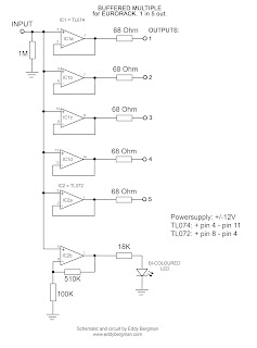
Here is the schematic drawing showing one stage. As you can see it's just 4 non-inverting buffers with all the inputs connected together. The module is just two of these on one piece of stripboard. Before 2026 I had the output resistors outside the feedback loop of the opamp and to get as little voltage drop over them as possible I used 68 to 100 Ohm resistors.
Here is the schematic drawing showing one stage. As you can see it's just 4 non-inverting buffers with all the inputs connected together. The module is just two of these on one piece of stripboard. Before 2026 I had the output resistors outside the feedback loop of the opamp and to get as little voltage drop over them as possible I used 68 to 100 Ohm resistors.
I have now integrated the output resistors into the feedback loop of the opamp so voltage drop will be compensated for and therefor we can use 1K resistors which is the best output impedance for this type of module.

(Last revised 26-Jan.-2026: put resistors inside feedback loop.)
Stripboard only.

Bill of Materials:

Here's the layout for the version with the bi-coloured LEDs. I updated this version with 1K output resistors that are part of the feedback loop so the opamp compensates for any voltage drop over the resistors,

Stripboard only.

BOM for the LED version:

Make sure you choose the bi-coloured LED's with two legs and not the ones with 3 legs. They won't work in this set-up. They must be two-legged. You may need to alter the value of the 18K resistors according to the brightness of the LED's you're using but I find 18K to be a nice middle value. Not too bright not too dim either. I've altered my own Buffered Multiple to include the LED function and These 18K resistors work just fine with the Red/Blue LEDs I'm using. But you can use 5K6 if 18K is too dim in your case.
I've had some kind feedback in the comments of the Buffered Multiple not working right with Gate signals in combination with the Behringer TD-3. The Gate pulse would stay high. The solution was very simple, just put a 1MOhm resistor between the input and the Ground. This is something I forgot but you must never leave an opamp input floating so there must be a resistor between the input and ground. I've adapted the schematic and put in the 1M resistor on the input. All the layouts are updated too.


LAYOUTS:
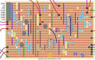
Here's the verified stripboard layout. Just two IC's and some wire bridges and resistors. I recently added de-coupling capacitors for the chips because it was kindly remarked upon in the comments below that they were missing and it is good practise to include them.

Stripboard only.

BI-COLOURED LED VERSION:
Wiring Diagram:


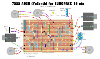
I didn't make a layout with just the cuts and wirebridges because that's easy enough to see in the layout above. Don't forget: DO NOT CUT the strips underneath the TL074's that connect pins 3 with 12 and 5 with 10!!!

Be aware that some opamps don't like input voltages that are near the voltage rail when they are used as voltage followers. I heard the TL07* series can jump to inversion in some cases so choose good quality opamps. I used the TL074 as you can see and never had any problems but I just thought I'd mention it.
 Stripboard only:


I left in 6 empty strips at the bottom so you can hot-glue the stripboard to the back of a Eurorack panel and use the side of the sockets for extra support, (glue stripboard to the side of the sockets) so the components will stick out above the sockets (or below the sockets, which ever way you look at it ^___^). If you have an other way of mounting it and don't need the extra empty space then just saw it off.
If you take a look at the demo video in the article about the "Really Good AS3340 VCO" you can see this Dual Buffered Multiple at work to the left of the VCO I'm demonstrating.
Below note E1 the Red light, which is positive voltage, doesn't light up but above E1 you can see it light up. (Note E1 = 1.4167 Volts) The higher the note, the brighter the LED gets and it can handle voltages as high as 15V without problems. Above the lowest 2 octaves the LED shines about as bright as it will ever get. For the blue part of the light the threshold for the LED is higher, about 3,5 Volt. So it will need a tiny bit higher initial voltage to turn on, but that's not really a problem. But for accuracy it's better to use Red/Green LED's because of the lower threshold voltage of the green LED vs the blue one.
I've added 6 times gain to the LED opamp stage so that the LED will start shining at the lowest of voltages. The 510K resistor determins the Gain. The formula for calculating the gain is 1+(510K/100K)=6.1
Of course you could also use two normal LEDs; one for the positive cycle and one for the negative cycle. It's up to you.
Of course you could also use two normal LEDs; one for the positive cycle and one for the negative cycle. It's up to you.
The extra gain of the LED output stage works very well in practise. The LED has quite a good range in brightness and thus gives a good indication of the strength of the voltage present on the outputs.
SCHEMATIC:

This module is very useful to have in your setup because sooner or later you're going to need at least one of these, just like you need at least one mixer/passive attenuator.
Here are a few pictures of the finished product. I made a little L-Bracket (also visible on the layout) so I could mount the board at 90° to the panel.

This is the version with the LED's installed. The right LED is displaying the voltage of the Gate signal which is +5V. The left LED is displaying the 1V/Oct signal which is a bit lower and thus the LED shines a bit dimmer.

The board up close. As you can see mine has more wire bridges because I forgot that some connections can be made directly under the IC. So I did it the hard way. The first picture below is the original module without LEDs. The second one is after I converted it and added the LEDs.

Because I added the LEDs later I had to use some jumpwires on the stripboard to connect it all together.

EURORACK VERSION.
SCHEMATIC:
This shows one part of the dual multiple. The second half is identical.

Here are a few pictures of the finished product. I made a little L-Bracket (also visible on the layout) so I could mount the board at 90° to the panel.

This is the version with the LED's installed. The right LED is displaying the voltage of the Gate signal which is +5V. The left LED is displaying the 1V/Oct signal which is a bit lower and thus the LED shines a bit dimmer.

The board up close. As you can see mine has more wire bridges because I forgot that some connections can be made directly under the IC. So I did it the hard way. The first picture below is the original module without LEDs. The second one is after I converted it and added the LEDs.

Because I added the LEDs later I had to use some jumpwires on the stripboard to connect it all together.

EURORACK VERSION.
Single buffered multiple with one input and five outputs.
This is one I recently built for my eurorack case. It has 5 outputs because I added a dual opamp for the LED and that uses only one side so I had an opamp left over which I added to the outputs. I used 68 Ω resistors from the outputs to the sockets to give the opamps a little bit of protection should a signal carrying cable be plugged into an output by mistake (opamps don't like that). I didn't use IC sockets for this build because I've run out of those. I soldered the IC's straight in but that works fine and it also means bad IC-socket contacts won't be an issue so it makes it more reliable.
EDIT: This is a project I did before I made the output resistors part of the feedback loop but I made new layouts incorporating these changes, so these are all updated.
This layout is verified.


The schematic below is the old version. I will update it later but all you have to keep in mind is that the output resistors are 1K, not 68 Ohm and they are included in the opamp's feedback loop so the connection to the negative (inverting) input is connected to the right of the resistors, not to the left as is shown here. That's the only difference. (see also previous schematic).

Here are some pictures of the finished eurorack module. It's 6hp wide (3cm) and 5cm deep. I used hot-glue to connect the stripboard straight to the back of the panel and next to the output sockets to which the stripboard is also glued for some extra support. Works very well and it's very sturdy. I soldered the power lead straight to the stripboard and also secured it with some hot-glue.
As you can see in the last picture there's one ground wire going through all the ground lugs of the sockets and the cathode leg of the LED. From there a copper wire connects it straight to the ground of the circuitboard. Don't rely on the conductivity of the metal front panel for grounding. Always connect socket grounds with wire to the circuitboard.
I later made an PCB based version using surface mounted devices (SMD). This was my fist time working with SMD components and I did all the soldering myself and altough it was a bit fiddly I managed to get the hang of it pretty quickly.


TRIPLE BUFFERED MULTIPLE.
As a little bonus for you, here's a Eurorack friendly version of a Triple Buffered Multiple. So 3 inputs and 12 outputs in total (no LEDs). If only one of the three inputs is used the signal comes out of all 12 outputs. If you use more then one input the signal gets divided up over the outputs. (See text on layout).
This module will run fine on either dual 12 or 15V so also useful for Kosmo sized systems.
If you want LEDs on this module you can choose to connect a Bi-Coloured LED to outputs A4, B4 and C4 and mount the LEDs next to those particular sockets or leave those 3 sockets out. The LEDs will probably pull down the voltage a bit on those outputs (but not on the rest.). Use a 15K resistor as a current limiter in series with each of the LEDs. Add decoupling caps if you wish over the powerrails nearest to each of the chips. A 100nF from + to ground and a 100nF from ground to - for each chip so 6 caps in total. There's enough room for that above each chip. You can use normal ceramic type caps.
[EDIT] This project was done before I decided to put the resistors inside the opamp feedback loops. See projects above.

I left in 6 empty strips at the bottom so you can hot-glue the stripboard to the back of a Eurorack panel and use the side of the sockets for extra support, (glue stripboard to the side of the sockets) so the components will stick out above the sockets (or below the sockets, which ever way you look at it ^___^). If you have an other way of mounting it and don't need the extra empty space then just saw it off.
Okay, that's an other one done. Number 25! A bit of a milestone for my synth build :)
If you have any questions or comments just leave them in the comments below please.
See you on the next one!