NB: Although I rate this as one of the best DIY ADSR's out there, there are some people having problems with this design. Even in my module the LED does stay on very dimly. Other people report problems with the envelope not returning to 0 Volt. In my case it works okay but I want you to be aware of this before you decide to build this. Should you have doubts then there is now an alternative to build.
Project 67, the Kassutronics Precision ADSR It also uses a 7555 chip, comes in eurorack size and works like a charm.
What does an ADSR or Envelope Generator do?


The normal envelope:

Inverted 0V to -10V:

Inverted +10V to 0V:

Here's a image showing the fastest rise time this ADSR can reach. It's just under 1 milliSecond or 980µSec.


The Envelope Generator is generally better known as the ADSR which stands for Attack, Decay, Sustain and Release. These are the four amplitude phases a note goes through when you press a key on the keyboard. If we didn't have this ADSR in combination with the VCA, we would constantly hear the oscillator sound but we only want to hear it when we press a key on the keyboard right? So as soon as a key is pressed down, a Gate signal goes into this ADSR to tell it to produce an Envelope Signal. This envelope signal then goes to the Voltage Controlled Amplifier where it opens up the VCA and so the amplitude of the envelope signal determins the volume of the sound coming out of the VCA.
The attack is the speed of the initial rise of the note, when you first press the key. Set it to zero and the sound is instantly there. Turn it open and the sound is going to take a while until it gets to full volume.
Decay is the time it takes for the note to go from the peak attack level to the sustain level.
Sustain is the level of the note as you keep the key pressed down. It is usually set a bit less loud than the peak Attack level. (If we set Sustain fully open it will be on the same level as the peak Attack level and then it won't matter how you set the Decay because there's nothing to decay to.)
Then we have Release and that is the amount of time it takes for the note to fade out once you let go of the key. So the envelope generator produces a signal that determines the volume of the note over time and this signal is being used by the Voltage Controlled Amplifier (VCA) which interprets it as an output level. In some Minimoog synths it is also called the Loudness Contour.
Now of course the envelope output is a control voltage so it doesn't mean that you need to use it for the above mentioned purpose. You can connect it to anything that can be controlled with a control voltage like the filter cut-off or the pulse width of a squarewave or even the pitch of an oscillator. This opens up a miriad of options but let's not get ahead of ourselves here. If you're just starting out with synth building, you need the ADSR to open the VCA and the fancy stuff will come automatically with more experience. And this ADSR is great for beginners but also for seasoned builders in need of a good working ADSR. This is my ADSR of choise really.
My building experience:
This is the fourth Envelope Generator I present on my website and I think this one is the first that worked as it should straight away. No trimmers to set in the circuit either. I just used the schematic from the Yusynth website made a layout and built it. On the website he has two versions, an old and a new one. I built the new one. I can say without any doubt that this design works if you want a good and reliable ADSR to pair with your VCA or to drive a filter. And because the circuit is so simple, even a stripboard version like this one would be robust enough to put in a rig you take on tour with you because, providing the panel is sturdy enough, there's practically nothing that can go wrong on the circuitboard. The only problem is the use of normal diodes which leaves a residual voltage in the capacitor preventing some VCA's from closing completely. I therefor recommend using Schottky diodes in this design.
This is the schematic. The opamp numbering on the schematic is different on the layout, I used the opamps in a different order. The numbering in red represents the Layout numbering.

And this is the stripboard layout I made for it. It is verified, I used it for my build and it worked first time. Because it's so simple a design I didn't even test the stripboard after building it. I made a frontpanel and wired everything up and then I plugged it into my synth and it just worked. I would advise to change the 1M resistor (R6) on the Gate input, from a 1M type to a 100K type right from the start. Might save you some troubleshooting later on.


Bill of Materials:


There's a LED to indicate the level of the envelope. The LED remains lit very dimly if there's no Gate signal present and the ADSR is at rest. This seems to be normal for this circuit.
This is the schematic. The opamp numbering on the schematic is different on the layout, I used the opamps in a different order. The numbering in red represents the Layout numbering.


You can see the components are rather stretched out over the stripboard. This is something I did in all my early projects to make troubleshooting easier. There's a smaller version further down this article that can also be used for Eurorack systems.
Here is the stripboard only view: 

If you want to add some extra outputs with buffers then below here is an extra layout that you can add to the ADSR to provide you with two extra normal outputs and two inverted ones. Of course you don't need to use the inverted output signal, you can use all four outputs for the normal signal. It doesn't matter what kind of signal is presented on the inputs, it will be replicated on the two outputs. (Two outputs for each input). This is an all purpose design so you can use this board for anything you like, even other projects like VCO's.

The wiring of the potmeters may look a bit strange with pin 3 left unused on three of the four potmeters, but I assure you that this is the way it should be wired up. Just follow the layout. It'll work fine I promise you. You can see in the schematic drawing that these pins are left dangling in the wind so that's what we do.
The ADSR triggers with a gate signal with a threshold of 3 Volt. The output envelope is 10Vpp. There's a manual trigger button on the panel (which is useful for testing). The envelope generator has two outputs. There's a normal output and an inverted output with a switch that lets you choose between +10V to 0V or 0V to -10V. There's also a switch to change the duration times with 'Fast' and 'Slow' settings. Use a DPDT ON-ON switch for the Fast/Slow function and a SPDT (ON-ON) switch for the Inverter voltage function. In Fast mode the duration for Attack, Decay and Release can be set between 1mS and 1Sec. In Slow mode they can be set from 5mS to 10Sec. These times are generated by the 1µF and 10µF electrolytic capacitors C4a and C4b. In the text on the Yusynth website it says to use Tantalum caps for this but I used normal Electrolithic Caps and this works just fine. I hate Tantalum caps anyway, they always blow up on me, LOL. If you want longer times you can install bigger caps. You could even take a 3 position switch and add a third cap of, for instance, 47µF to generate really long times. I haven't tried this myself so I can not guarantee it works but I don't see why it shouldn't.There's a LED to indicate the level of the envelope. The LED remains lit very dimly if there's no Gate signal present and the ADSR is at rest. This seems to be normal for this circuit.
Make sure you use three logarithmic 1 Mega Ohm potmeters for Attack, Decay and Release. Otherwise it will be difficult to set the parameters accurately. For Sustain we use a normal linear 10K potmeter.
It's interesting to note that all the 1 Mega Ohm potmeters control time parameters (Attack time, Decay time and Release time) while the 10K linear potmeter controls a level. The Sustain level.
You can run this envelope generator on a dual 12 Volt powersupply without any changes only the envelope output levels will go from 0 to 8 Volt instead of 0 to 10 Volt.
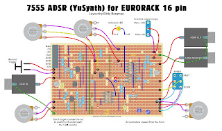
EURORACK LAYOUTS:
You can run this envelope generator on a dual 12 Volt powersupply without any changes only the envelope output levels will go from 0 to 8 Volt instead of 0 to 10 Volt.
EURORACK LAYOUTS:
I recently made layouts for Eurorack in both the 10 pin and the 16 pin versions. In the 16 pin version the Gate input is connected to the eurorack-connector's gate pin but also has a separate input socket. If you want to disconnect the Gate signal from the eurorack-connector if you're using the normal input socket, then you must solder the gate connection from the eurorack-connector to the switch of the gate input socket instead of using the wirebridge as shown on the layout for the 16 pin version.
(Remember there are also eurorack Gerber files available at the bottom of this article.)
I've had confirmation that this layout works. So it is now officially verified.
Eurorack 10 pin version:
A very observant reader drew my attention to the fact I had forgotten the connection from pin 6 of the 7555 to pin 14 of the TL074 so I updated the layouts and tucked that wirebridge in underneath the chip socket of the TL074.
I used Schottky diodes in this design because that works much better. I advise to always use Schottky diodes in Envelope Generators because it will help with cutting down any DC offset voltage at the output. The BAT43 is what I used. As mentioned before, beware that the numbering of the opamps is different from the original schematic. I used the opamps in a different order, numbered in red on the schematic.

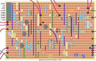
Stripboard only:

Cuts and wirebridges seen from component side. Mark the cuts on the component side with a black Sharpie or Edding pen and then stick a pin through the marked holes and mark them again on the copper side. Then cut the strips at the marked positions with a sharp hand held 6- or 7mm drill bit.

Bill of materials, will also work for 16 pin version except you must use a 16 pin Eurorack power connector obviously ;)

Eurorack 16 pin version. The diodes are marked as 1N4148 in the layouts below but use Schottky diodes instead! Like mentioned in the 10 pin version and the BOM above.
Stripboard only:
Here are some screen shots from the oscilloscope. These are from the 'Kosmo' sized ADSR but that shouldn't matter in the end result of course:
The normal envelope:

Inverted 0V to -10V:

Inverted +10V to 0V:

Here's a image showing the fastest rise time this ADSR can reach. It's just under 1 milliSecond or 980µSec.

TROUBLESHOOTING:
If you experience problems with this ADSR like the LED is always on and the VCA does not close then here are some tips for you suggested by people in the comments and on the Facebook group.:
Put a 100 Ohm resistor in series with diodes D4 and D2 (to the release and decay potmeters)
Put a 4K7 resistor in series with the LED. (This didn't help for me, my LED is always a tiny bit on)
Replace all 1N4148 diodes for schottky diodes.
Reduce the value of C3 from 10nF to 4,7nF or even 1nF.
Use a 500K potmeter for Release if you have trouble accurately setting the release time.
Replace the 1M resistor R6 with a 100K resistor. R6 is located at the Gate input
Well, that's all there is to say about this project really. A very satisfying build because everything worked as it should right from the start. The panel potmeters work over their complete throw, unlike some other E.G.'s I built, and you can set all the parameters very easily. If someone would ask me what ADSR to build I would certainly recommend this one. You can easily add on extra outputs if you so desire. You can add a TL074 for instance and wire up some extra outputs and/or inverted outputs. That's easy enough to do.
Okay, to close off, here are some pictures of the finished product. I made a copper bracket to keep the print in place behind the panel. That way I could use just one M3 bolt. I soldered all wires straight to the copper side.


Okay, to close off, here are some pictures of the finished product. I made a copper bracket to keep the print in place behind the panel. That way I could use just one M3 bolt. I soldered all wires straight to the copper side.


EURORACK VERSION WITH LOOPING OPTION:
Now there's also a Eurorack version of this ADSR that has a looping function included. Paul Darlington, a member of the EB Facebook group, came up with this brilliant addition to the schematic. Here's a link to the files he posted on Github: --- CLICK HERE ---
You are not allowed to use these files for commercial purposes! They are published under Creative Commons 4.0 license.
Here's a picture of the faceplate of Paul's ADSR module:

Okay, that's all for this article. If you have any questions or comments please leave them in the comments below or post them on the special Facebook Group for this website.
Hey Eddy had a question about switches, are you using on-on-on for dpdt and spst or on-off-on, thanks again. Does it also matter really what switches you
ReplyDeleteuse between the two?
Good question, I should have mentioned it. Use DPDT for the fast slow and SPDT for the inverter voltage.
DeleteThey are the ON-ON type btw. I should have mentioned that in the first reply. ^^
Deleteappreciate the photos of the finished boards, nice to have a real life reference when you're just starting out.
ReplyDeleteThank you! I'm glad you're finding it helpful. If you run into any problems building this, just let me know and I'll try and help. I love this ADSR. It works really well.
DeleteHey Eddy! What kind of capacitors do you recommend for C[1-5]?
ReplyDeleteI used polyester capacitors but it's not critical like in a filter. Any type will work fine as long as it's the right value.
DeleteHello, do you prefer this design over the digisound-80 ADSR? And if that's the case, why so? Which one would you say has more precision?
ReplyDeleteYes I prefer this one, eventhough the Digisound is my main ADSR. It has some quircks. It doesn't work exactly as it should. Especially automatic mode. The 7555 one is more precise too I think.
DeleteThank you for the reply. I decided to build both this one that is based on a 7555 and a different ADSR that is based on the Digisound 80-10, it seems to have a very interesting feature.
DeleteOkay cool! :)
DeleteHey Eddy. great Work here!. would it be possible to get the Gerber files?
ReplyDeleteThanks a lot Jonas
Hi Jonas. Can you give me you email address in the comments here? I will delete the comment as soon as I noted your email address. Then I will send you the ZIP file with the Gerbers.
DeleteThanks for the reply. I'll send the Gerbers on to you. I'm afraid this is the only project I have Gerbers for. They were provided by a reader who offered them too me free for publication which was very nice of him :)
DeleteThis comment has been removed by the author.
ReplyDeleteHi, does this schematic work with other synth formats (specifically Metric 5U in my case)? or is it only for Eurorack? hopefully this question makes sense.
ReplyDeleteI think this will work fine with a 5U system. The Kosmo system 4,5U and uses a dual 15V power source but this ADSR will work on both dual 12V and 15V and it can handle signals upto +/-10V so that should be fine.
DeleteHey Eddy, I would love to build this ADSR, but I can't seem to find the BS170 or it's equivalents available anywhere. Are there other options for the MOSFET that are easier to get? Even better if anyone can give me a tip for where I might be able to salvage one. I have some boards to get components from. Thanks!
ReplyDeleteThey are still available. Here's an eBay listing. These will do fine: https://www.ebay.com/itm/324361348621
DeleteHello, I found that buffer circuit here and I was thinking about to build one to split my VCA output signal. Maybe this is a rly dumb question but for what is the 1k ohm resistor needed ? And I guess it would be good idea as an VCA-signal splitter to add a couple capacitor to every op-amp output.
ReplyDeleteThank u for ur great work!!
I take it you mean project Ex-4. The 1K resistors at the end protect the opamp from short circuit and they determin the output impedance. Most outputs in the synthesizer world have an output impedance of 1K. Yes you could use this for your VCA. I'm not sure what you mean with the capacitor. You could put a cap over the resistor from pin 6 to pin 7 of the opamp. That would supress any voltage spikes in the signal. Don't put any caps in series with the output. That would defeat the purpose of the quad offset board all together because it would stop any offset voltage and it would work as a filter in itself.
DeleteFirst of all thank u a lot for the fast answer!
DeleteI'm sorry for my rough questions. I still have to learn to formulate my questions and thoughts better, so other people can follow better.
I got the point with the impedanceand (shame on me for somehow that stupid question) but at least I learned something about the tipicall impedance values of eur modules.
I learned at university that u put a cap at the output of audio amp to terminate the dc voltages, like a 10uF cap so u dont have a filter or better said only a minimal filter effect. I saw the same cap at the end of ur VAC (build-part: 10). So I thought it would be good to add them to the cuicuit (project Ex-4) too after the resistors if I want to use this one as an audio signal splitter ? :)
I want to point out that I'm not trying to argue against u It's just a question and I'm trying to write down my thoughts behinde it... I still have to learn a lot and I'm gald that there are people like u who share there knowledge !
Kind regards.
Please don't apologize. There's no need. There is no such thing as a stupid question in my book. About the cap, you are right if you want to use it for audio only you can put a cap in series with the output to block DC voltages. Normally in synthesizer builds we only do that if it's in the schematic. We don't just add caps always because sometimes, like with VCA's, we want to be able to use them for Control Voltages and in those cases we don't want caps in the circuit. So you have to be really sure about what you're going to use it for. In the VCA you mentioned I put them in because I had some offset voltage in the output that I needed to get rid of (as far as I remember).
DeleteI'm glad you're enjoying the website. If you have any more questions feel free to ask them. :)
Heya Eddy, hope this reaches you in good spirits my friend.
ReplyDeleteam currently in need of a EG to put together this weekend and narrowed 'er down to this one. defo gonna go dual EG in the "luxurious" KOSMO format .(doing dual everything now) your layouts provided the essential building blocks in my modular system and I"m diggin it man.
its really great to be able to build this stuff at home efficiently, we really do live in amazing times.
Thank you so much for that my friend! I'm glad the website is so useful for you. Keep on building!
DeleteHello!
ReplyDeleteI recently built this module, but it seems like the signal doesn't turn off at all. In fact, the LED stays on all the time.
I already changed the transistors and ICs, but it seems that the problem is not there.
Did anyone have the same problem? Does anyone have a solution?
Hi! I'm having the same problem ':D
DeleteThere is a section on this page dedicated to troubleshooting this build right underneath the pictures of the oscilloscope ;)
I have a question about the solutions mentioned there. Specifically this one: "Put a 100 Ohm resistor in series with diodes D3 and D2 (to the release and decay potmeters)"
You (Eddy) suggest to add 2 resistors in series with diodes 2 and 3. Within the schematic D4 indeed comes before the decay potmeter. D3 though comes after the attack pot and the switchable parallel resistors. I'm assuming with D3 you mean the diode at position P/R 28 on the stripboardlayout?
Probably important to mention that I have built the 16-pin Eurorack layout.
Thanks in advance!!
Oh, I forgot to mention the capacitor C3 being 10nF both on the schematic and the stripboard layout instead of 10µF as the last troubleshooting step suggests. What value should the capacitor be?
DeleteI'm sorry it's been a long time since I built this so I can't immediately recall these solutions and how they work. I believe they were suggested to me by others who built this project. If you need answers then i would suggest posting in the Facebook group
DeleteGood call on the value of C3! I have changed it in the text. Thank you for that!
Delete@Marijn, I have not published your latest comment as you instructed. I hope you find the answer.
ReplyDeleteaccording to the fixes on the facebook group schematic I just searched for the 100ohm resistor goes on d2 and d4 not d2 and d3. hope this helps someone
ReplyDeleteThank you for that. I corrected it in the text.
DeleteHi Eddy, I'm hoping you or someone else may have some ideas to help me with his one - I'm pulling my hair out trying to figure out how to get this module to work properly. I've now built it from scratch twice and I'm having the same exact result so I'm at a loss. I'm building the eurorack 10-pin version. What's happening is similar to what other posters have described but with maybe some differences:
ReplyDelete1) The "resting" state of the module is not at 0V - the output is always up several volts (or down if I'm using the inverted out). The baseline moves a little up and down depending on the position of the attack and release pots. As soon as I turn it on, it rises to this level.
2) Attack and release appear to work - when I trigger the envelope, the rise and fall from A/R is as expected and the fast / slow and inverted are correct.
3) Decay / Sustain don't seem to make any difference at all regardless of how I position them. The envelope always goes open to the same amount and stays steady until I release the trigger. The steady state is around 8-10v I think. I can confirm that on my scope tomorrow.
I've added the troubleshooting fixes mentioned above - schottky dioes, additional resistors on the led and R/D, and changed C3 to 1nf. No change for any of these updates. I've replaced all of the parts multiple times, and as I said, started from scratch to make sure I didn't mess up the stripboard. I'd love to get this to work, but I'm running out of ideas! Thanks!
I'm sorry you're having so much trouble with this one Roland. I really don't know what to suggest to you because you seem to have tried all the alternatives. You're not alone in having problems with this build but when I built it it all worked fine. It's really weird. I would just abandone this project and try an other design.
DeleteThis comment has been removed by the author.
DeleteThank you for that suggestion Uweee. I've added it to the troubleshooting tips.
Delete