A simple LFO with pulsewave (with variable pulse width) and a seamless transition between a Ramp wave, Triangle wave and Sawtooth wave using one potmeter. With LED rate indicators and Speed and Shape controls.
Well what more is there to say about this LFO. It's such a simple design that I could easily fit two of these on a small piece of stripboard and still have it small enough to fit a normal Eurorack case. The circuit is derived from the 'Utility LFO' by Ken Stone which is a larger version of this LFO.
I now also have a project for the complete Utility LFO and it's even smaller than this one and a panel width which is only 1HP wider at 9HP. Go to project 50 for that.
This LFO is still useful on its own though because it is so small. It can easily be incorporated into other projects as an on-board LFO for instance.
The depth of this module is 55mm. I made the panel 4CM wide, that's 8hp, and I put the potmeters to one side leaving enough room to glue the print straight to the back of the panel at a 90° angle using hot glue. All the output sockets fitted nicely next to eachother at the bottom.
Naturally you can just as easy build this module in the Kosmo size and run it on 15V. If you do, you need to keep to the resistor values as they are in the schematic, not the layout because as I mention further down, I changed the 1K output resistors to 1K8 to get a nice +/-5V output signal. If you power this with 3 more volts you probably don't have to do that. Do some testing first to make sure though.
I tried my hand at using Falstad recently and tried to make a simulation of the complete Utility LFO circuit and it was surprisingly easy to do.
So here is my very first ever Falstad simulation: --- CLICK HERE ---
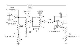
Here's the schematic drawing of the dual LFO circuit:
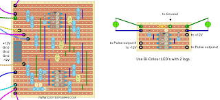
The module consists of two of these circuits on a single piece of stripboard. I placed the LEDs on a separate piece of stripboard with a dual opamp, the good old TL072, and I used bi-coloured 3mm LEDs in red and blue. I drilled two 3mm holes to the left and in the middle of the first two- and last two potmeters for the LEDs and glued them in place with hot glue so the little print sits over the potmeters. See pictures below for illustration. Btw, you can use any dual opamp chip for this circuit as long as the pinout is the same; like the TL082, NE5532, LM358 etc.
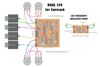
LAYOUT:
Here is the layout I made for this Dual LFO. As always, the layout is verified. I used it for my build. I placed the Eurorack powerconnector on the left side for better access. In my build it's on the other side and very near the panel. Not a good place for a power connector but you only find these things out when you start building it. See, I make the mistakes so you don't have to LOL! (I hot-glued the print to the back of the panel with the righthand side closest to the panel.)
Stripboard only:
After doing the first tests I found the output voltages a bit on the low side. They were just +/-3,24V so I decided to experiment with the 1K resistors between the outputs and ground. I tried several values and I ended up using 1K8 resistors. That brought the output voltages to a nice +/-4,8V. Almost 5V so that's perfect for eurorack. If you want that voltage to be even higher in your LFO then experiment further with making the resistor(s) between the output socket and ground even higher in value.
I wanted to make one of the LFO's a bit slower than the other to give me a wider overall range so I used a larger capacitor for LFO number one. I used a 147nF and that made it perfect for my needs, between 0,2Hz and 10Hz. In the layout both timing caps are 47nF though.
TECHNICAL DATA:
Here are some measurement results for this Dual LFO:
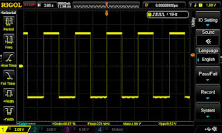
Duty cycle of squarewave is 5% to 95% this varies a bit with the frequency but not more then 2%.
Lowest frequency: LFO-1 = 0,219Hz LFO-2 = 0,653Hz (changed timing cap of LFO-1 from 47nF to 147nF)
Highest frequency: LFO-1 = 9,82Hz LFO-2 = 34,2Hz
Output voltage is +4,8V or 9,6Vpeak-to-peak. That's after changing the 1K resistors in the schematic for 1,8K ones. Otherwise the voltage was just 3,2V and 6,4Vpp.
Current draw: positive: average 12mA max.: 18mA
negative: average -13mA max.: -18mA
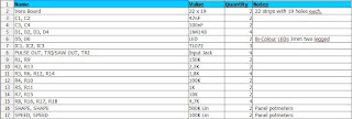
Here's the Bill of Materials:
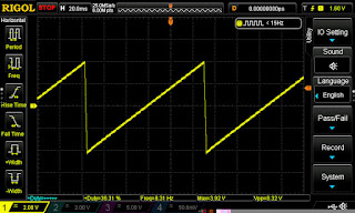
Here are some screenshots from the oscilloscope with some measuring data underneath the images. Some images may still show the lower output voltage but that's been fixed:
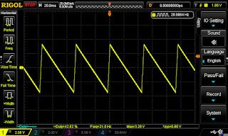
The following are screenshots from the oscilloscope showing two signals, one from each LFO, being combined in a simple passive multiple. A squarewave and a triangle wave each at different frequencies. The results are pretty cool looking:
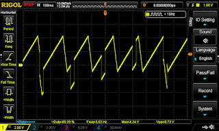
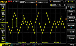
In the top picture you see more of the waveform in the positive voltage region and very little below zero Volts. You can set that with the shape potmeters to your own liking or best sounding result. As you can see this makes the Dual LFO module much more versatile as a modulation source. Plenty to experiment with.
PICTURES:
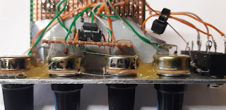
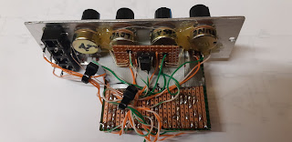
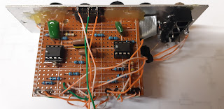
Below are some pictures of the print. I took these before I changed the 1K resistors to 1K8 ones. In the top picture and the 3rd one you can see how I mounted the little print with the bi-colour LEDs. The print rests above the middle two potmeters and the LED's are bent backwards over the sides of the stripboard and go straight into the holes in the panel and are secured with hot-glue. The little print itself is not mounted in any way. It just relies on the LEDs to keep it in place.
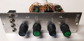
This time, instead of spray-painting the panel I decided to keep it blank aluminium and I used an engraving tool to put the text on. That didn't work too well and it didn't look good at all so I printed some labels I made in Photoshop, laminated them with Scotch Tape and put some double sided sticky tape on the back and I put those on the panel. That looks much better.
TRIGGER OUTPUT
A few days after completing this build I added a trigger output to this module. I connected it to the squarewave output of the second LFO (the faster one). I thought it might come in handy to have a trigger source. You can see in the picture below how I did that. It gives of both positive and negative trigger pulses of 5V and a length of about 4mSec. If you're thinking of putting in a diode to only get positive pulses forget it. That won't work. It'll kill off the pulses completely. If you turn the Shape potmeter the positive and negative pulses will move further away or closer to eachother. Just like the rising and falling edges of the squarewave with different pulsewidths.
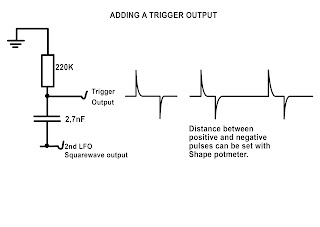
(The above drawing actually translates to a high pass filter with a cut-off frequency of 268Hz. So it filters out the actual square- or pulsewave and only lets through the initial harmonics of that wave, creating this spike pulse trigger response, but you can forget about this theory. This is not important.)
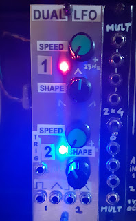
Here's a look at the final panel with trigger output. I just made some labels with text to put on the panel. Looks better than the engravings.
One other thing worth noting is that because we have two LFO's on one board, they will very slightly influence eachother. What I mean is, if you have one LFO running at almost twice the speed of the other, the faster one will adopt some multiple of the rythm of the slower one if you set the speed to some value close to that. That's a form of resonance and I won't get into the technicalities of that but it's quite easy to set an LFO at twice or 4 times the speed of the other because they share the same circuitboard. It's the same idea as when you have a group of people walking together and they all start to walk at the same pace. That's also a form of resonance. Don't think this will be an obvious thing to observe. The occurrence is very subtile.
Okay, that's number 47 done! A very useful little module and I saved a few bob by building it myself instead of buying a dual LFO module. Okay it doesn't have any fancy extra's like synchronization but that's okay by me. I think I'll mostly be using this as a clock source and some random modulation. That's why I made both LFO's run at different frequency ranges.
If you have any questions or remarks about this or any other project on my site please comment below or post in the FACEBOOK GROUP for this website.
If you find these projects helpful and would like to support the website and its upkeep then you can buy me a Coffee. There's a button for that underneath the menu if you're on a PC or Mac. Or you can use this PayPal.Me link to donate directly. All donations go towards the website and projects. Thank you!
Interesting the business about the resonance locking behavior. I recently built a dual LFO based on a somewhat similar design from Kassutronics, and I don't see similar behavior. Aside from the differences in the circuit design, I did mine on a PCB. Perhaps the stripboard strips are behaving as better antennas than the PCB traces. I thought about the possibility they were coupling through the TL072 you use for both oscillators' indicator LEDs but with its high input impedance it doesn't seem that likely to me. Anyway if I were in the mood I could probably argue that behavior is a feature, not a bug...
ReplyDeleteYes I think you're right in that, because it's stripboard, there may be some more capacitance between the copper strips, that might have something to do with it and the fact that it's such a simple design. Anyway, it's a very subtle thing and you do need to tweak the pots carefully but I found that when I was close to getting one LFO running at multiples of the second LFO they sort of locked in place of their own. I certainly don't see it as a bug. It can be very useful in certain patches :)
DeleteThanks Eddy! I just finished my first module of yours, the Dual LFO. All good! I’m happy I chose a bigger cap for one of the LFOs. I’m happy 😃
ReplyDeleteExcellent! I'm glad it was a succes. :)
DeleteHi Eddy, again, great project! Do you have any idea for a small tweak and make this as an oscilator? Maybe with no tuning, no 1V/octave, just higher frequency? Maybe for fm modulating or hard syncing to a master vco? And could there be a cv input for mixing between waveforms?
ReplyDeletethanks:)
I'm not sure about a CV input for the mixing but to get higher frequency just use a smaller value capacitor for the 47nF. Maybe you can put a Vactrol over a potmeter to get Voltage Control over the shape of the waveform but you'll have to do some experimenting.
Delete