Thursday, 5 March 2020

Synthesizer Build part-22: RING MODULATOR (Yusynth design).

An excellent ring-modulator to serve as an extra source of weird sounds. This one is simple to build and works very well.

Next to the filter and the FM and Sync capabilities of a VCO, I think the ringmodulator is one of the most important ingredients for sound shaping in any synthesizer and an often overlooked one. No synth should be without one. The ring-modulator was something I always wanted to include in my DIY synthesizer and I was thinking of doing it the old fashioned way with audio transformers but they are very expensive. So I went looking for designs that used semiconductors and came across the Yusynth design. I ordered some MC1496N IC's from a shop near where I live because I didn't want to wait for components from China, what with the Corona virus going on etc. and I wanted to be sure I got real MC1496's and not fakes, which is so often the case with IC's from China. The MC1496 is a chip you will find in many vintage synthesizers and also in the Macbeth studio systems Dual Oscillators for Eurorack (a favourite of Colin Benders). They have a built in ringmodulator that uses this chip. Anyway, I got the chips the next day and I set out to make a stripboard layout.
A ringmodulator takes two signals and multiplies them. If you input just one signal you won't get anything out because if you multiply by nothing (zero) the outcome is nothing. So both inputs need a signal going in for this to work. (That's why you can use Ring-modulators as crude VCA's when switched to DC mode) One is called the Carrier wave and the other is called the Modulator wave. You can modulate the amplitude of the carrier and so get AM modulation. You can get the most beautiful results from this circuit. It can produce very cool bell like sounds or very gnarly AM modulated sounds. You can spend hours experimenting with it. I myself usually combine the output from the ringmodulator with the output from one of the VCO's going straight into a mixer so I can add both signals up and then send that through a filter and/or the lowpass gate and boy do you get phat sounds like that!

Click here to go to the original Yusynth article.  

Schematic for single ringmodulator:

Here is the (verified) stripboard layout I made from it. The original schematic is for a double ring modulator but I only built one. But it's just the same circuit repeated. I used this layout for my build so it is tried and tested. Note that the electrolytic capacitor on the AC output jacks has it's polarity reversed from those on the AC inputs.


Stripboard only:


Bill of Materials:
There different types of 1496 chips for sale, like MC or LM, but the letters in front of the numbers don't matter. They just indicate which firm produced the chip. They will all work fine in this circuit as long as they're 1496's.


TUNING THE RINGMODULATOR:


You can find the tuning procedure on the Yusynth website. I'll describe the procedure here:

There are two trimmers to adjust: A1 and A2. These trimmers are used for cancelling the input signals. The settings are quite simple, you will need a signal generator that delivers a sinewave signal with a 10V peak to peak (+/-5V) output amplitude. You can also use a VCO in your synthesizer to do this. 
The Yusynth website talks about audio amplifiers but it's easier to use a VCO with sinewave and a VCA from your synthesizer to do this and make sure you connect an oscilloscope to the output signal with a frequency counter enabled so you can set your VCO to 1kHz.
Here is how to proceed :
  1. Set your audio generator (or VCO) to 1kHz and set the output level of the generator to 10Vpp.
  2. Connect the output AxB of the module to an audio amplifier or your VCA. Be sure to set the input potentiometer of the amplifier to a low value: the output level of the module is 10Vpp and most of the audio amplifiers expect an input level that doesn't exceed 1Vpp. If you use a VCA it'll be okay. (We need a line level output signal so we can listen to it through speakers but if you connect an oscilloscope you can just watch the signal)
  3. Connect the signal generator to the input A with a capacitor (AC-INPUT). There, you must hear the 1kHz signal at the output AxB.
  4. Adjust the trimmer A2 so that the 1kHz signal can no longer be heard at the output.
  5. Disconnect the signal generator or VCO from input A and then connect the signal generator to the input B  with a capacitor (AC-INPUT). There, you must hear the 1kHz signal at the output AxB. Adjust the trimmer A1 so that the 1kHz signal can no longer be heard at the output.
Now the module is ready to operate. A last check can be done by connecting the 1kHz signal to both inputs A and B (AC inputs): there you must hear a signal which is twice as high in frequency (2kHz).
It will be a bit of a balancing act to get these signals on the zero volt line on your oscilloscope. Turning one potmeter might create an slight offset voltage that you can trim away with the other trimpot. If all is well you should easily be able to tune the ringmodulator in a few minutes.
If only one input is used there should be no output (because something times zero = zero) and if there's a signal on both inputs you'll get the two signals multiplied out of the output. That's why a ringmodulator can also be used as a crude VCA.
When I first tested my ringmodulator I kept measuring a negative offset of -9V on the output if I stuck a signal into input B. It turned out that my TL072 was faulty. I stuck a new one in and all was well.

PICTURES:
Ring modulation is a very interesting way of combining two frequencies and can get very complex very quickly if you use waves that have a lot of harmonic content like squarewaves. More on the theory involved is here on this Wikipedia page about ring modulation.

This is one of only two ringmodulator designs on this website because this one is just so good. You don't need to fiddle with audio transformers and diodes. The chip might be difficult to get for some people but my local electronics store had them in stock. They don't sell many of them.

I didn't think I could fit any more modules in, but this one was just small enough to go into the wood panel above the modules, next to my Sample and Hold module. Here's a look at the finished panel and how I fit the stripboard behind it with a little copper L-Bracket I made myself and soldered onto the stripboard.


Ignore the sawdust specks in the bottom picture, LOL. I took it just after putting the module in and the synth was covered in fine dust.
Okay that's another one done. This is getting to be quite a big and powerful "sound design machine." It's about time I made a new case that I can put on top of this synthesizer so I can keep building ^___^

If you have any questions please leave them in the comments below!


Wednesday, 4 March 2020

Synthesizer Build part-21: ARP2600 LOWPASS FILTER (4072).

The famous ARP 4072 VCF. The best sounding filter of any I built so far! With verified stripboard layout.

A word of warning right at the start; this is an advanced project, not for beginners. You need to know your electronics and you also need to have a good oscilloscope.

The ARP2600 is my favourite synth from the early 70's. It's been used on so many iconic records.
In any synth the filter is the defining factor in the creation of the sound and after tackling the ARP's Envelope Follower I thought it was time to try out the famous 4072 filter. ARP has had a number of well known filter types. The 4012 (4035 for Odyssey) which was a Moog type ladder filter over which they got in trouble with Moog for patent infringement. The 4023 two-pole filter of the early Odyssey synths. Then later came the 4072 (the one we're going to make) for the later ARP2600's. The ones with the orange labels with white lettering. These had a fault at first due to miscalculation, which limited the bandwidth of the filter to below 10kHz. This was later fixed with a few component value changes. And then there's the 4075 which was the filter used in the later ARP Odyssey's.
If you want to build this filter there's really only one schematic you can turn to and that's the Yusynth schematic. So I set to work making a layout. I first tried just starting at the lower left of the schematic and building the layout up from there. Within minutes it turned so complicated I couldn't make heads nor tails of it. So after an other unsuccessful try I came to version 3 of the layout and this time I decided to place all the semiconductor components neatly on the board first. All transistors in a row on top and the two chips in their own space underneath and wire it all up that way. This worked fantastically and after a days work I had a layout that looked really good and, more importantly, turned out to be faultless right from the get go.
I was blown away when I tested the finished filter. Of all the filters I built, from the Moog Ladder Filter to the Steiner-Parker, there is no filter that sounds as good as this one. Now I love the Steiner filter and it sounds awesome but this one just has more quality and better resonance control. More meat on the bone if you know what I mean. It sounds how a synthesizer should sound. But of course this is all a matter of personal perception. Mind you this filter, at least the one I built, has less output volume. It's a bit quieter than other filters which is why I suggested a upgrade of the gain in output opamp. More on that further in the article.

BUILD PROCEDURE
Like I mentioned at the beginning, this is not a project for beginners. It's reasonably complicated and you need to work very methodically and do things in steps. First map out all the cuts in the copper strips with a Sharpy and cut the traces accordingly. Then solder in all the wire bridges and then solder in the components. Keep counting the holes and make sure everything is placed exactly like on the layout, otherwise you will run into trouble with space on the board and things end up not being connected right. I worked from left to right soldering it all in and checking every connection with a powerful loupe. And in the end, of course, it didn't work straight away. It turns out I had forgotten to cut four copper strips near the 1V/Oct trimmer. After I cut those the filter suddenly sprung to life and started making sounds that instantly reminded me of the ARP2600.

SCHEMATIC:
Here's the Yusynth schematic. It looks a bit weird but the LM3900 really operates on negative voltage, in this circuit. 


LAYOUTS:
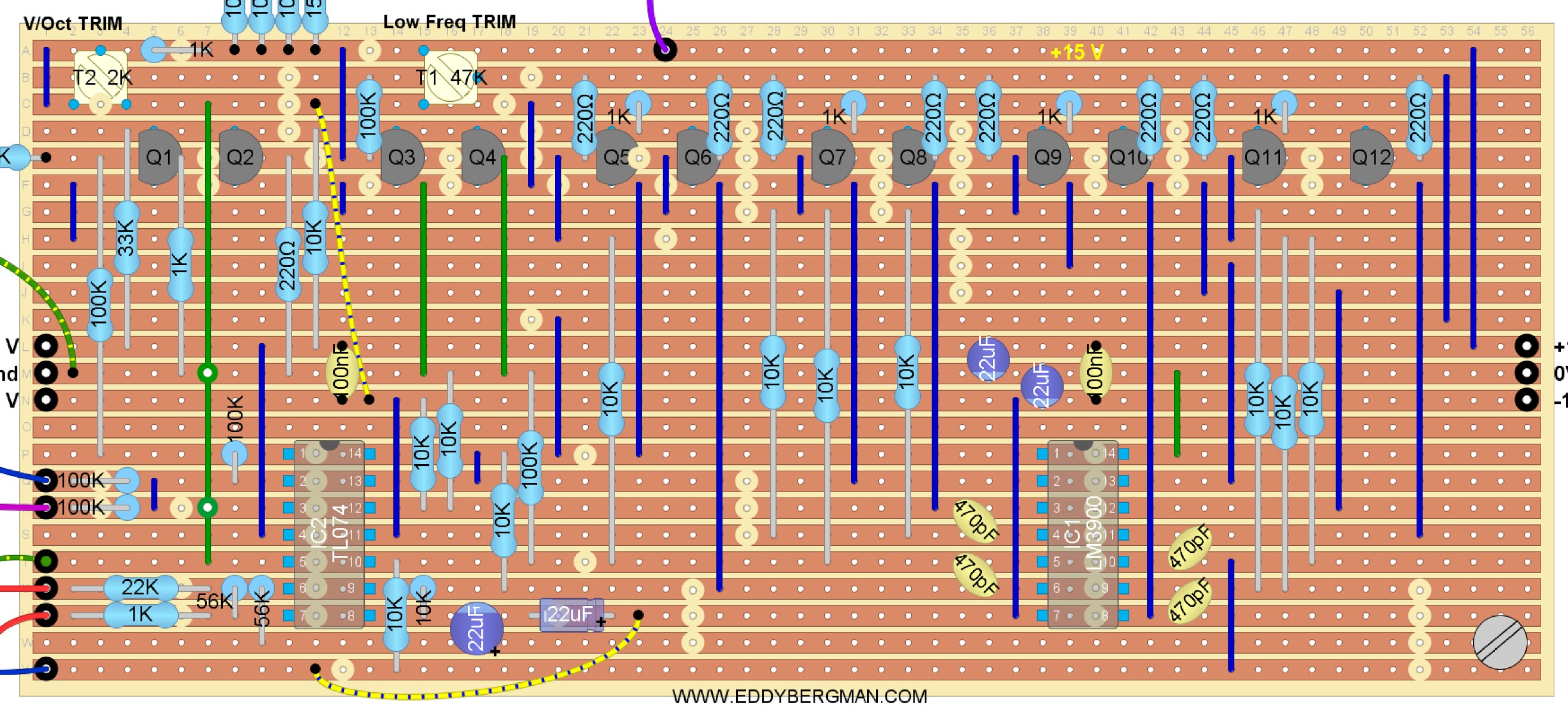
And here's the layout. Like I mentioned before, the layout is verified because it's the one I used for my own build. (All potmeters are shown from the front with shaft facing you). 
Addition: I've had confirmation from multiple readers that this layout has been used successfully. 
To increase the gain I strongly advise to change resistor R41 from 56K to 100K. R41 is the 56K resistor over pins 6 and 7 of IC-2 at the bottom left (from hole U-8 to V-8). Otherwise the volume will be a bit too low.


Stripboard only:


Sometimes you'll see a cut in the copper strip overlapping a component in the layout above. I've done that on purpose so the cuts are easily visible. The layout is pretty complicated especially for beginners because there are so many cuts to be made, so I want things to be as clear as possible. 
Below is the cuts and wirebridges layout. Mark the cuts with a Sharpie or Edding pen on the component side and then put a pin through the marked holes and mark them again on the copper side. Then cut the traces at the marked positions with a sharp hand held 6- or 7mm drill bit.
Cuts and Wirebridges component side:


To make it even easier here's a layout showing just the cuts that need to be made in the copper strips. This is seen from the COPPER SIDE!:


Bill of Materials:


If you don't trust yourself to build this on Stripboard then here's the PCB design for this filter. You can find it on the YuSynth website along with all other necessary information. Click the link below for that.

http://yusynth.net/Modular/EN/ARPVCF/index.html

SOME NOTES ON COMPONENTS:
There are 12 transistors in this filter and they need to be 6 matched pairs. I simply matched them on Hfe value with the transistor tester on my multimeter and that seemed to be good enough because the filter works fine. Officially they need to be matched over the value of Vbe, so if you measure the voltage drop over the Base-Emitter junction, and match them that way, that will be the best method but you'll need to set up a little test rig for that on a piece of stripboard.
Here's the circuit for matching PNP transistors. Use a cut in half DIP8 IC socket to stick the transistors in and easily switch them. You'll need a +/-12V dual voltage source for this setup.
If the transistors are matched the voltage measured between both emitters should be zero (0V).


Make shure you give the transistors time to cool down after you held them between your fingers. I always blow on them to cool them down faster. A match of 0.3 mV or lower is good enough.

The four 470pF capacitors need to be high quality and also closely matched in value. I used polystyrene caps for those. I even matched the 220 Ohm base resistors so they all had the same value. In my case they are all 216 Ohm.  The CV inputs all have 100K resistors on the inputs and a 150K resistor on the wiper of the Cut-Off Frequency potmeter. I didn't have room for them on the stripboard so I hung them over-board so to speak. In reality I soldered those resistors straight to the wipers of the potmeters and in case of the 1V/Oct. straight to the input jack. Then I put some heat-shrink tubing over them and after that I put some heat-shrink tubing over all the wires from one input together so there's never any tension on the resistor itself. This works fine. Of course, if you use a bigger piece of stripboard you can accommodate those resistors on the board itself. Or you can use a small piece of stripboard, solder the resistors on that and connect it to the main board with wires and then use some hot glue and a plastic spacer to glue it to the main stripboard. Lots of options :-)
The resonance potmeter needs to be a dual- aka stereo potmeter. I didn't have one but luckily my neighbour, who repairs audio equipment, had one laying around but it was a logarithmic potmeter. I put it in anyway and it worked like a charm. :) For the trimmer potmeters you can use a 50K for trimmer T1 if you don't have a 47K. In fact, it can be any value from 20K upwards because it's just connected between plus and minus 15V so the actual resistance isn't important for the working of the circuit. But don't forget there is 30 Volts across that trimmer so don't use a value below 20K to keep the current flow down. For trimmer T2 you can use a 2K instead of a 2.2K, but you must keep close to the recommended value for that one because it is part of the input bias for the transistor Q3. I used a 2K on my print and this works fine.

ABOUT TUNING:
This filter has a 1 Volt per octave input connection to make the resonance follow the chromatic scale if you want to use the filter as a sinewave oscillator with resonance fully open. The filter sounds better over all if you use that connection although it is not necessary for the filter to function. There's a trimmer (T2) for the 1V/Oct and the way I set it was to listen to the filter's response while going over the keyboard from low to high. If it is set wrong you'll hear the notes become all muddled up and out of tune at the higher end. If you set the filter potmeters in such a way that it self-oscillates, then the resonance pitch will follow the keyboard scale. So you need to tune the filter so that the self-oscillation is in tune with the keyboard notes if possible. I myself however did not tune it that way. I simply tuned it so the notes sounded ok over all the octaves and left it at that. That's good enough for me and the filter works fine. I don't think the self-oscillation of the filter will track well over multiple octaves anyway, but again, I didn't try that so I may be wrong. The filter is an Alan R. Pearlman design (ARP) and they are usually really good designs. Let me know in the comments if you managed to get self-oscillation tracking over the octaves, please!
The other trimmer is the Low Frequency trim-pot (T1). It needs to be set so that the output wave at the lowest end of the keyboard, and with the Cut-off pot turned all the way counter-clockwise, is a nice sinusoidal bass tone, at least, that is the way I set it. I'm not saying that this the way to do it. I'm simply saying, this is how I did it.
The frequency cut-off potmeter is wired up in such a way that it opens up and lets through the high frequencies when you turn it clockwise and when you turn it counter clockwise it cuts off more and more of the high frequencies making the sound very deep and low.
The values of the potmeters for CV IN and for the audio inputs are not critical and you can use anything from 10K to 1M for those because they are just level potmeters. For the audio potmeters the schematic says to use logarithmic ones but in reality linear will work fine too. It's log because it's audio. Like I mentioned before, I used a logarithmic stereo-potmeter for the Resonance control because that's the only thing I had but it seems to work very well eventhough the schematic says to use a linear type. It probably wouldn't matter what value you use for the Frequency Control either but I'd stick to the recommended 50K or 47K for that one. (I used 100K's for the CV level control potmeters.)
Don't forget to solder the 100K resistors, for the CV inputs, to the wipers of the potmeters or to the input on the stripboard, and don't forget either that the resistor on the wiper of the Frequency Control potmeter is a 150K and not a 100K one! (A mistake I initially made.)

PICTURES AND DEMOs
Here are some pictures of the finished stripboard. This is an early version that has one more jump wire than the new layout. I realized I had a copper strip that was not in use so I used it to replace a jump wire. You can see I marked out the cuts in the copper strips with a black felt pen. I also marked out the 0V/Ground strip with a black line on the component side of the stripboard. Marking out the ground helps to prevent mistakes.


Here's a little video with a demo of what the filter sounds like, taken right after I built it in. Remember when I filmed this it was the first time I played around with this filter so this is just a simple demo of the sounds it produces. At this point in my synthesizer building journey I hadn't even figured out that you need to connect an ADSR to the filter's CV input to get that characteristic filter sound. I just have an LFO connected here. Oh well, I've learned a lot since this was published ^____^


In this second video (which I filmed later) the filter CV-1 input is connected to the little 7555 AD/AR with the big arcade button. This kicks up the cutoff frequency of the ARP filter as soon as a key is pressed and then releases it pretty quickly thereafter. The AD/AR is set to trigger mode so it gives an Attack/Decay response.  The filter is fed with a single squarewave from the VCO. I think you'll agree it sounds amazing. Like a synth should sound. With apologies for my poor keyboard playing :p 
This is a new video posted on the 12th of November 2020:


This filter can also produce those helicopter sounds that you can hear in the beginning of 'Apocalypse Now'. (Francis Ford Coppola had an ARP2600 himself.) All you have to do is turn the cut-off frequency counter clockwise and connect an LFO with a sawtooth wave to the CV input, set to the frequency that the rotor-blades of the helicopter would have and turn the resonance counter-clockwise too. You can add some noise too on Audio IN 2 if necessary.

One little attention point you must remember when using this filter. It's possible to overload this filter with audio in so much that the resonance won't work at full capacity. I had this happen to me where the resonance wouldn't produce the famous whistling sound and I had been trouble shooting for a day changing out the IC's, checking transistors, replacing the capacitors until I finally found out I had the input level set too high (The Audio-1 level potmeter on the front panel). I turned it back by a quarter and everything was back to normal. I'm telling you this so you don't make the same mistake. ^___^

This is what the panel looks like now. I've touched the lettering up a bit because it was all crooked (and it still is I guess, LOL) so it's good enough for me. What's important is what this panel represents; the best friggin' filter I've ever built!! :)


Okay that's it for now.
To finish off this article here's a fantastic documentary about the history of ARP Instruments by YouTuber Alex Ball who has the best synthesizer channel on YouTube in my opinion. Enjoy!


That's it for this article. I hope you liked it.
If you have any questions or remarks please put them in the comments below or on the special Facebook Group for this website.


Wednesday, 12 February 2020

Synthesizer Extra's No. 01: SIMPLE AD/AR using the 7555

A fantastic little AD/AR envelope generator that is super easy to build and works very well.  Perfect little adition to the DIY synthesizer.

I was looking for a better AD/AR design than the one I had built and used upto now and I came across the Thomas Henry design. Here is the schematic.
This design uses the CMOS version of the NE555, the 7555 and it can be built on a piece of stripboard that is the same size as the LMNC version that I first used.

If you're new to all this; AD/AR stands for Attack Decay/Attack Release. It's a little Envelope Generator creating a control voltage that can open and close a Voltage Controlled Amplifier (or you can drive a filter with it. There are lots of options.)
In the picture below is the stripboard layout I made for it. I added all the features that Sam Battle has in his design, like the Arcade push-button with internal light and I added a little thing of my own, an option to double the output voltage of the Envelope from 0 to +5V to 0 to +10Vpp. I always find it handy to have a bit of extra charge on the envelope if I want to use it to control a filter for instance. You can of course connect a potmeter to the +10V output and so turn the output amplitude up or down from 0 to 10V. That way you can do away with the +5V output altogether. Since I already made and wired up the panel for this, I couldn't use the potmeter option. I simply exchanged the old stripboard for this new one and soldered all the wires back in place. You can also wire up the opamp in such a way that it inverts the envelope. That would be easy enough to do. As a final extra I put in buffer stages for the envelope output, for both the +5V and the +10V output. You could also wire one of those up to be an inverter. Lots of options here. One thing that is different from the LMNC version is that the Arcade Push Button won't work as long as a key is pressed down. The Gate signal has priority in this design.

The layout below is an early version and although it works fine, it is a bit messy. So I made a new layout which you can find a bit further down the article. I'm leaving the old one up in case someone who built it needs to reference it for troubleshooting or something.

SKIP THESE 2 LAYOUTS AND GO FURTHER DOWN TO THE UPDATED LAYOUTS TO BUILD THIS PROJECT.

Beware if you are using standard 24 x 56 holes stripboard, that the layout only goes from A to U not to X. So only 21 strips!


(Last revised: 1-March-2020: Changed attack and release pots from linear to logarithmic. 4-Oct.-2021: Cosmetic changes to layout.)

Here's a close-up of just the stripboard:


Bill of Materials:


Here's a look at how fast this little AD/AR is and it is super fast! It reacts to the Gate signal with practically no delay what so ever as you can see from these scope images. The risetime is about 12 µSec. The same as the risetime of the Gate signal (Gate = yellow, AD Out = blue). The gate signal has a bit of a skew in it half way up. That's due to some circuit specific stuff elsewhere in the synth but not really relevant because we are zoomed in so much it's practically instant. I mean, it's 12 millionth of a second in total:


UPDATED LAYOUT:
I made an updated version of the layouts above. I built it and changed the old one for this new one and everything works as it should so it's verified.  In the previous layout the output stages and 0 to 10V is a bit clumsy, although I guarantee that it works fine! The layout below is just a bit neater because I gained some knowledge over the past year and applied it here:


Beware if you are using standard 24 x 56 holes stripboard, that the layout only goes from A to U not to X. So only 21 strips instead of the usual 24!


SCHEMATIC:
Here is the schematic for this version. As you can see I added two buffers (which is a bit overkill but I wanted to use all the opamps available) and one opamp with a gain of x2 to get a 0 to +10V output. The buffers help to prevent this AD/AR from 'hanging' if you use it with inputs that have a bit of a low impedance (see text below). Both outputs are connected to a switch so you can choose between them. You could of course connect sockets to both outputs, instead of the switch and have two outputs permanently available, a 0 to +5V and a 0 to +10V. That's up to you.


The AD/AR works as follows: In AR or Gate mode, the Attack remains high for as long as you keep the key on the keyboard pressed down. After you let go the Release kicks in and the signal will fade out in the time you have set with the Release potmeter.
In AD or Trigger mode the Attack/Decay cycle still needs to have been completed before you can trigger it again but as soon as the Attack cycle has been completed the Decay kicks in, regardless of whether the key is still pressed down or not. For fast trigger sequences the Attack and Decay need to be set to short times because it won't trigger again until the cycle is completed, and that's perfectly normal.
So with the Attack a tiny bit open and Decay/Release fully closed you get a powerful envelope pulse of either 5V or 10V depending on how the switch is set.
In Gate mode you can have both Attack and Release fully closed to get fast short envelope pulses as the video below will demonstrate.
If you build this circuit with separate inputs for Trigger and Gate, and you feed it both at once, the Gate signal will take priority.

Here are some pictures of the stripboard using the new layout. I had made a mistake at first because I forgot this layout only had 21 strips instead of 24 so I made some cuts in the wrong place. That's why I placed the warnings with the layouts. And that's why there are some horizontal wirebridges in the lower ground strip (bottom black line).


12V vs 15V:
A little word on operating this from a dual 12V power supply. It will work but you'll need to change one resistor at the output. (R7 on the schematic). The 2K2 (R7) becomes a 3K3. This is necessary to give pin 6 on the 7555 the correct threshold voltage. I myself put in a 5K trimpot for R7 so I could experiment with the threshold voltage. It turned out that changing the resistance value of R7 mainly influenced the amplitude of the Envelope. In other words, you can set the initial envelope voltage with it. So after I learned this I took the trimmer potmeter back out and put in a 3K3 resistor.

The 'hanging' issue:
Because the resistor voltage divider at the original output influences how this AD/AR works I decided to add some extra buffer stages at the end, to stabilize the working of the circuit. I noticed that impedance differences, when connecting it to certain filters in my synth, can make the AD/AR hang sometimes. The release won't activate like it should, probably because the threshold voltage on pin 6 is disturbed somehow. I didn't want to rebuild the whole stripboard so I used a little piece of stripboard with just a single TL072 on it and buffered the +5V aswell as the +10V outputs. I stuck it onto the main board with hot-glue. It now works perfectly. No hanging or anything. I incorporated these buffers on the stripboard layout so they are now part of this design.

This design works a lot better for me than the LMNC one. This AD/AR reacts to trigger signals with an amplitude of +4 V and upwards and gate signals from +1.8 V and upwards with a maximum frequency of at least 60Hz. For triggering to work well, you need to open up the Attack a tiny little bit. The circuit is so fast that the envelope pulse shuts off before it has time to reach full potential. I tried different things to fix this little issue but I wasn't successful upto now. Anyway, it's nothing serious having to turn up the Attack a tiny little bit when using Trigger pulses. When you use Gate signals there's no problem.
I do strongly advise you use a logarithmic potmeter for the 1 M Attack potmeter. I used a normal linear one first but had trouble setting short attack times accurately. I've now put in a logarithmic one and it makes a world of difference. Works so much better. I really need to change the Release potmeter into a Logarithmic one too. That would make it much easier to dial in the Resonance or Cut-Off frequency when I use this to activate a filter. For the 4,7µF capacitor you can use a normal electrolythic capacitor. You don't need to use a Bi-polar capacitor in this circuit, unlike the LMNC one. You can put in extra electrolythic capacitors in parallel with the 4,7µF cap. to stretch the Attack time to the maximum length you want. I put in a 3,3µF and two 1µF caps for a total of 5,3µF which gives me almost 10 seconds maximum attack time. If you need longer Attack times just put in a 10­­Âµ­F cap.

Here are some technical specifications:
Minimum Attack time: 692 µSec
Minimum Decay time: 248 µSec
Maximum Attack time: 6 seconds with 4,7µF cap.  9 seconds with 5,3µF (which is what I installed)
Maximum Decay/Release time: ±30 sec.
Maximum input pulse frequency: ±60Hz

Here's a link to the Electro-Music Forum page that deals with this design:
http://electro-music.com/forum/topic-61297.html

Here's a little demo video of this AD/AR in action:


This second video shows one way of using the AD setting (trigger mode) of the AD/AR to control the cutt-off frequency of the ARP2600 filter. The Attack is fully closed so the instant a key is pressed the envelope voltage opens up the filter and then the Decay sets in and slowly closes the filter off as the envelope voltage fades down to zero. Watch the big blue light and listen to the effect on the sound.


The LED inside the Arcade push-button is connected to the +10V envelope output with a 4K7 resistor. It shines nice and bright. There's also a yellow LED on the panel between the input and the output. That one is connected to the output jack with a 1K resistor. It shines normally when you use +5 V out and extra bright when you use the +10 V output level. This is just a handy indication of how the output switch is set. It also reacts faster to pulses than the LED inside the push-button so it's a better indicator for that too. The LED was already built in so I thought I might aswel use it like this. :)
The Arcade push-button switch, which is the manual trigger, is fed with half the positive rail voltage (+7,5V) by means of the voltage devider formed by the two 68K resistors. I thought that was better than giving it the full whack of the +15V rail voltage. You can of course use other values for these as long as they are both the same. If you want to feed the switch with a different voltage then you can calculate that voltage as follows: Say R1 is the resistor coming from +15 V and R2 is the resistor going to ground. V = 15/(R1+R2)*R2
The arcade push button will not work as long as a Gate signal is present!!
Gate takes priority over manual trigger, just so you know that.


Okay, conclusion time: This design is a big improvement over the LMNC simple AD/AR and I can highly recommend using it. It works very well with patches where you feed it a fast trigger signal to control drum modules for instance. The switch which lets you choose between +5V or +10V output works perfectly fine but if you want more control just build it with the output controlled by a potmeter like I mentioned before. I do recommend you include the extra buffers at the end. They will insure that this AD/AR works perfectly under any condition. The only tiny little down point is that in Trigger mode the Attack needs to be a tiny bit opened to get a full envelope pulse. With Attack fully closed in Trigger mode, the pulse you get on the envelope output stops so fast that is doesn't have time to reach the full voltage potential. You could say it's too fast for its own good. You can see this happening on the oscilloscope. You get really fast pulses that don't reach the full voltage before they're cut off again. In Gate mode you won't have this issue and it works just perfectly. I really like this design and I highly recommend building it.

Here's a picture of how I added the buffer stages by glueing on a little print with a single TL072. This saved me from having to rebuild the whole thing.


Finally, for my own record keeping purposes, here's two pictures of how the finished synthesizer now looks, with two new VCO's and the Envelope Follower and the little oscilloscope of course:


Okay that's it for this article.
This article isn't really part of the synthesizer build itself so I named it 'Synthesizer Extra's'.  That's the header I will use for articles describing enhancements and changes to the original synthesizer that I build in the past 19 articles.
If you have any questions please leave them in the comments or post them on the special Facebook Group for this website. Okay, see you on the next one.


Friday, 7 February 2020

Synthesizer Build part-20: ARP2600 ENVELOPE FOLLOWER with pre-amp.

An fantastic external input module, derived from the famous ARP2600 synth. It produces a Control Voltage, Gate and Trigger pulses from an audio signal and it has a clean audio output at synthesizer level for further treatment. In fact it offers you a third modulation option besides the LFO and the Envelope Generator (or ADSR). You can also use the envelope or trigger output as a sync pulse to sync different modules together and it also works as a gate extractor. This one is a 'must have' in your system.

Although I pretty much finished the first stage of my synthesizer build when I wrote this article, I got inspired to try and add one more module to the case after watching this documentary about the ARP2600. I always wanted some sort of external input module in my synthesizer and in this documentary they talk about the opening of a famous song by The Who called 'Who Are You'. Pete Townshend plugged his guitar into the ARP's Pre-amplifier and through the Envelope Follower to get the effect you can hear in that song. So I started to look into Envelope Followers and asked on Facebook for schematics. It turns out these schematics are all variations on the same theme and look and perform very much the same. That's easy to understand as they all need to perform the same task.

NOTE Feb. 2025: AS THIS WAS ONE OF MY EARLY PROJECTS THE DESIGN OF THE INSTRUMENT PRE-AMP CIRCUIT WASN'T REALLY THAT GOOD SO I HAVE NOW UPDATED THIS ARTICLE WITH NEW SCHEMATICS AND NEW LAYOUTS.

I have PCBs available for this project. They include all the functionality of the stripboard version and they're sized: 42mm by 99mm. I built one up myself to test it out and it works beautifully.

WHAT IS AN ENVELOPE FOLLOWER?
Now what is an Envelope Follower I hear you ask and to be honest, I didn't know myself until a week before starting this build. An Envelope Follower (or EF) creates a Control Voltage who's amplitude follows the amplitude of the input signal. So the control voltage sort of follows the contours of the volume of the input signal. This is nicely illustrated by the oscilloscope pictures below. And as an extra it also produces Gate and Trigger signals if the input volume (or amplitude) passes over a certain threshold, so this can also be used as a Gate Extractor of some sort. So in other words, you can input external audio signals and get control voltages, gates and triggers from them plus a clean amplified audio output. Just what I wanted.
I did some research and it turns out that Alan R. Pearlman (founder of ARP Instruments Inc.) won a prize for designing a tube based Envelope Follower in 1948 and he wrote a thesis about it for his senior year at Worcester Polytechnic. I dug around and found the ARP2600 service manual in which I found the schematic for the Envelope Follower with pre amplifier. The chip they use for the preamp is the 1339-01 which is long obsolete I believe (I couldn't find it) so I decided to make the pre-amp with the venerable LM386 at first. But I later found out that these chips shouldn't be used for pre-amps because they have a low impedance output meant to power loudspeakers or headphones. Not ideal, so I based the instrument amplifier of my updated version on the pre-amp that Ray Holmes used in his Envelope Follower module. That in turn is a Ken Stone design. For the electret microphone pre-amp I stuck with my previous 1 transistor design because it works so well and it's such a simple design. I really like using it.

HOW THE CIRCUIT WORKS:
Here's how this circuit works (quoted from the ARP 2600 service manual):
A1, CR2, CR1 and A2 comprise a full wave rectifier for the audio signal. The positive portion of the wave, on pin 6 of A1, goes through CR2 and into the non-inverting input of A2 (pin 3). The negative portion of the wave passes through CR1 into the inverting input of A2 (pin 2) so that the output of A2 is always positive. The rectified signal is then filtered by R12-15 and C7-10 and then amplified and buffered by A3. 
R12 to 15 and C7 to 10 form a 24dB/Octave low pass filter. This is straight from the original ARP schematic and it works very well. The filter's cut-off frequency is 53Hz. This filter makes sure the high frequency audio part of the input signal, which is rectified by the two diodes, is filtered out and we are left with a low frequency voltage that follows the amplitude of the audio input signal. The signal is attenuated quite a bit by this filter but is then boosted again by the almost 10x gain of opamp 3 with the 10Meg feedback resistor (R17). Ray Holmes lowered that value to 4,7Meg to run this circuit on +/-12V so I followed in that and it works very well.

Here is the original schematic from the ARP2600. (The microphone pre-amplifier it uses is the standard datasheet circuit for the 1339-01 chip):


As you can see it doesn't have a 'Gate out' or a 'Trigger out' so I took those functions from the PAiA schematic and I came up with the schematic below which I used for my build. The component numbering follows the numbering on the original ARP schematic, as far as possible.
With the circuit below the gate output will be around +8V. I changed the value or R24 (4K7) and R25 (51K) in the layouts below to produce gate and trigger pulses of exactly 10V. The circuit was designed to work on +/-15V so these alterations had to be made to make it work on +/-12V.


(Last revised: 20-April-2026: Made completely new schematic with new instrument pre-amp based on Ken Stone design. Later changed value of Gain potmeter to 100K instead of 10K.)

Here's the KiCad schematic. I made the changes necessary to have this work on +/-12V


THE INPUTS EXPLAINED:
In the schematic I drew above, I put in all the different points at which we can input signals of a different level or amplitude. 
The Envelope Follower has three inputs that are normalled together.
The first input is the most sensitive, this is the electret microphone input. It uses a transistor amplification stage that goes into the instrument amplifier via the socket switch (normalled). The on-board microphone on the panel is also connected to this stage but that connection will be broken if you insert a cable into the mic input. Beware that this input has a +12V voltage on it to feed the electret microphone so this input is only to be used with those type mics.
The second is an instrument amplifier. If you want to use an instrument like a guitar, you can plug it in there and the connection with the microphone preamp will be broken. You can also connect a dynamic microphone to this input, like a Shure SM57 for instance or audio equipment with a line output..
The instrument amplifier is normalled to the direct input of the envelope follower. You can input a signal directly into the E.F. if that signal is at the synthesizer level (+/-5V to 10Vpp).
I've also added a LED to the Gate output to get a visual indication of the working of this circuit which is very useful to have, especially to see if the input is clipping.

So one more time for clarity: the three different inputs are there to accommodate different input LEVELS! 
- The input for the electret microphone can handle tiny signals in the 10 to 100 millivolt range which then get amplified by the transistor pre-amp to around 2Vpp and then by the instrument pre-amp to boost it up to 20 Volt peak-to-peak max. before they go into the envelope follower. The electret input has voltage on it! (up to +12V) The next two inputs do not!
- The second input can handle input levels from 100 millivolt up to the 2 volt range, for use with guitars or dynamic microphones for instance, and this gets amplified by just the instrument pre-amp to boost it to synthesizer levels for input into the envelope follower. It has a potmeter to adjust the Gain. Btw, I advise to use a 100K instead of the 10K on the schematics for the gain potmeter.
- Finally, the third input does not have any pre-amplification so this input can only be used for signals that are already in the +/-5 to +/-10 Volt range (10Vpp to 20Vpp) like synthesizer or drum machine signals.
At first the idea behind the 3 different inputs was to serve as a substitute for the x10, x100, x1000 preamp range switch that was on the original ARP2600 Envelope Follower. In the original ARP2600 the range switch was a 3 way switch that changed the feedback resistor over the pre-amp opamp with a choice of 10K, 1K and 100Ω. 
Now, with this new version of the Envelope Follower, with the new instrument pre-amp design, it has a 100K gain potmeter over the instrument pre-amp opamp and that can also be seen as a substitute for the gain switch in the ARP2600 but having the 3 different inputs makes this module much more versatile. It also allows the pre-amp to be overdriven to get distortion like Pete Townsend used in the song 'Who Are You' by The Who.
Using the LED for guidance to set the levels, you can extract a Gate and Trigger pulse that follows the beat of the input audio and so trigger a drum machine or synchronize a sequencer to the beat.

All inputs are normalled together so when nothing is connected to the inputs, the envelope follower gets a signal from the electret microphone mounted on the panel. That connection is broken when you insert a microphone into the mic pre-amp. The output of the mic pre-amp goes through the instrument pre-amp to the envelope follower input. That connection in turn is broken if you plug something into the instrument input and then that connection in turn gets broken if you connect something directly to the envelope follower input. So the envelope follower input always gets the right amplitude range from whatever you want to use as input source. On top of that it has its own level control so you always get the correct levels.

Here's where the socket switch is located on the 3,5mm mono sockets I always use for all my projects.

 
Leading the envelope signal into a VCO doesn't sound very good, at least not when the envelope is produced from the human voice. It's better to use it for a VCA controlling volume. After considerabel testing I added one feature. An envelope smoothener. It's just a 47µF cap over the output jack which can be switched on and off. It is effectively forming an extra lowpass filter with a cut-off frequency of 3.4Hz, filtering out the higher frequency spikes and pulses. This is in fact the same as the ARP2600 'LAG' control. More about this at the bottom of this article.

LAYOUTS:
This is a new and verified layout design which I made in Februari 2025. If you need the old ones, contact me on Facebook and I'll send them to you. I kept the microphone preamp from the previous version because it works so well. I tried the one used by Analog Output in his E.F. module but I couldn't get it working.
Wiring:


The resistors R20 and R21 (33K and 47K) determin the voltage threshold of the Gate and pulse outputs. They form a voltage divider that gives off +5V to pin 13 of the TL074 which is set up as a comparator. Any envelope signal higher than +5V will produce a gate and trigger signal. If you want to change that threshold you can change R20 for an other value which you'll have to calculate. (These resistors are located at the top left of the stripboard) however there's no reason to do that. You can create more or less gate and trigger pulses by varying the input level and gain. 
The voltage amplitude of the actual gate signals is determined by resistors R24 and R25. Using the values in the schematic the gate and trigger pulses will be around the 8 Volt. I changed the values of these resistors in the layouts to 4K7 and 51K which produces pulses of exactly 10 Volt. The previous version had them at 10 V too. (these changes are also in the Bill of Materials)
Stripboard only: 


Cuts and the wirebridges. This is seen from the component side.


As ever, mark the cuts on the component side with a permanent marker like a Sharpie or Edding 3000 and then stick a pin through the marked holes and mark them again on the copper side. Then you can cut the copper strips at the marked places with a sharp hand held 6 or 7mm drill bit. With this method you have the least chance of making mistakes.

Bill of Materials following the numbering of the schematic.  There are some components with duplicate numbers but don't worry about that. The right amounts are in the bill of material.
Instead of a 10K potmeter get a 100K for the gain control.


TEST RESULTS / SCOPE IMAGES:
And finally some test results in the form of screenshots from my oscilloscope. 
The trigger pulse takes about 100 mSec to die out completely but if you want that time to be shorter just put in a smaller capacitor for C12, the 3n3 that is at the Gate to Trigger junction in the schematic drawing. The Gate and Trigger outputs are about 10Vpp. 
All scope screenshots are from the new version. The yellow line is the envelope output, the light blue is the microphone preamp output (clean audio at synth level), the dark blue is the Gate or Trigger output and the purple is the instrument preamp output.
You can see that all traces are set to 5V/Division except the light blue which is 1V/Div.


In the picture below you can see the gate signal at a nice +10V like it was with the old one. All I did was change R24 from a 15K to a 4K7 resistor to up that voltage.


Here's an example of the function of the 'smooth' switch. One side is smoothed and the other is normal.
In the screenshots below dark blue is the trigger output, purple is gate, yellow is envelope out and cyaan is audio output.


Notice the lag or phase shift that occurs if you engage the smooth option. That's why the original control on the ARP2600 was called 'Lag'. It introduces a 90° phase shift.


Here's a close-up of the picture above showing the lag a bit clearer. Compare the peak of the cyaan (light blue) coloured waveform with the yellow and you'll see a slight delay in the yellow peak.


The different level controls work very well and I can get Gate, Trigger and useful Envelope voltages from this circuit while wispering in the microphone or, giving it more attenuation, I could be shouting in the microphone, makes no difference. The LED will indicate when it clips by being on continuously so you simply attenuate more and that's it. With all these different inputs and level controls this circuit can take an enormous range of input signal voltages.
One thing to remember, the Gate and Trigger signals need to go into high impedance inputs like opamps (and that's usually the case anyway, so no problem). If you pull any current from them their voltages will drop.

Here's how to make a simple hand held electret microphone with a 3,5mm mono socket and a patch cable:


Just solder the mic to the socket. Electret microphones can be bought on eBay for around $ 5,- for 20 pieces. They're really cheap. Get the ones with two legs. You'll see that one leg is electrically connected to the case. That's the minus or ground pole.
Here's a link to an eBay listing: https://tinyurl.com/5n6bfhsy

Pictures from the build proces:
Wirebridges put in.


All components put in. Don't mind the wires, they were for testing.


Here's the panel I made for the Eurorack sized module. It's 14hp wide (7CM) which is a size I almost always use because it means I can mount the stripboard flat behind it, making the module less deep than if the board is mounted at a 90° angle.


Finished module. I built an electret microphone into the panel itself which is switched off when an external microphone is connected to the socket. Above the gate and trigger outputs there's a little 3mm blue LED. (blue was the only color I had left.) It lights up when a gate pulse is created and it also makes for a great clipping indicator because if it stays on all the time you know you will need to lower the level or gain. Very useful actually. If you patch the audio output into the input of a module like Mutable Instruments Rings, you can get some very cool sounding string plucking sounds.


The normal/smooth switch connects a 47µF capacitor to the envelope output to smooth out radical changes in voltage. It acts as a lowpass filter with a cutoff of 3Hz.

Backview. The module is just 3,5CM deep. The stripboard is held in place by one M3 stand off and the rest of the stability is provided by the wiring itself.


I also made a version for my DIY synth with Kosmo sized panels, this time using a PCB I designed for this circuit. It works just fantastically. With this module I used a 100K potmeter for the pre-amp gain stage which means I can really overdrive it like the original ARP2600 version. I re-used an old panel for this so I didn't have room for a Lag switch but the PCB has a connection for that.


Here's Ray Holmes' video about the envelope follower he built which follows the same principle I used in mine:


Here's a link to Ray Holmes (Analog Output) article about his envelope follower module:  --CLICK HERE --

Okay, that's an other one done!
I hope you enjoyed this article and if you have any questions please put them in the comments below or post them in the special Facebook Group for this website. You can follow this blog to keep up to date with the latest posts.
See you on the next one!